High power LEDs:
The recent availability of high-power LEDs provide an alternative to Lasers for high intensity light sources that can be easily modulated. Because the only practical means of modulating most light sources is through intensity (or "amplitude") modulation, these modulation schemes invariably the varying of the current through the LED to achieve the desired modulation.
As with any electrical device, there are some practical current limits that must be observed in order to avoid destruction of the device. One of these is excess voltage (from static discharge, for example) but most high-power LEDs are rather well protected in this regard.
Excess current, however is another story!
The Luxeon III LEDs are rated for a (nominal) 3 watts of dissipation, but some of the devices in the series (the Red, Red-Orange, and Amber) are actually rated for continuous operation at a bit over 4 watts - somewhat higher power than the other colors in the Luxeon III product line.
Comment:
The Luxeon I, III, and IV products have
been phased out and have only limited availability as "new-old stock",
but many other high-power LEDs are available from a wide variety of
manufacturers. In the discussion below note that the current
values are specific to the Luxeon III series and should be scaled
appropriately for the LED that you intend to use.
For the remainder of this discussion, we will be assuming the use of the Red, Red-Orange, and Amber Luxeon III devices with the higher power capability.
Given an "infinite" heat sink, the absolute maximum continuous current permitted for these devices is 1.544 amps with a peak pulse current of 2.2 amps although the parameters of that pulse (e.g. width and duty cycle) are not noted.
Through testing, I have determined that a properly heatsinked Luxeon III will probably tolerate continuous operation at 2.5 amps for a short period (30 seconds or so) without damage Other experience has shown that at a current of somewhere between 3 and 8 amps, the bond wire(s) on the negative lead of the Luxeon will fuse (open) and render the LED inoperable.
 |
Having accidentally made several Luxeon III's "inoperable" I decided that all optical transmitters will contain circuitry to limit the current to a value that will be safe enough to protect the LED during short-term accidents.
A few notes concerning use with Luxeon LEDs:
- Red, Red-Orange, and Amber Luxeon I LEDs have a much lower peak current rating - about 550 mA. At this lower current, R1 would need to be above 2.5 ohms and R2/R3 would be adjusted accordingly. If a precise value of R1 (around 2.2 ohms) can be selected, R2 and R3 can be eliminated and the "adjust" terminal can be connected directly to the "load" side of R1. This lower current/voltage also means that the total drop of this circuit will be in the 3.5-4 volt range at the limiting current.
- Philips is apparently phasing out the Luxeon I, III,
and V lines in favor of the lower-power Luxeon Rebel
devices. Since I have not used those other
devices, the techniques described here may not directly
apply unless the maximum current is appropriately
adjusted. For the time being, however, the Luxeon III
devices are still available from various sources. The
Luxeon Rebel devices have a peak current of 700 milliamps,
so a 1.8 ohm resistor in place of R1 (with R2 omitted and
the "ADJ" terminal connected to the "load" side of R1) would
be appropriate.
- With "ultra high-power" LEDs - that is, those with maximum
peak currents in the 10's of amps - the following methods
may not directly apply as the LM317 and similar 3-terminal
regulators simply can't handle the current! In those
cases, current-limited supplies, a slightly more elaborate
overcurrent protection circuit and plain, ordinary care and
common sense are your best defenses against accidentally
"killing" an LED!
The simplest current limiter is a series resistor. While simple, it's somewhat costly in terms of power dissipation and its effectiveness (both in preventing damage and in allowing normal operation) is somewhat dictated by the available supply voltage: Too high a value and the LED cannot be driven to full current. Too low a value and the LED is not adequately protected. If the supply voltage is lower or higher than expected, the effects are similar.
A solution to this problem is the use of a common 3-terminal voltage regulator, the LM317. This device is commonly used to regulate voltages, using a simple resistive divider to set the output voltage, but it can also be used as a fairly precise current source.
Even though the "official" rating of the LM317 in the "K" (metal TO-3) or "T" (TO-220 "tabbed) packages is 1.5 amps, it is perfectly capable of operating at somewhat higher currents than this. One of the features of the the LM317 is its built-in current limiting and a quick peek at the data sheet will reveal that its internal ("room-temperature") current limit is typically 2.2 amps - but it could be anywhere from 1.5 to 3.5 amps. In testing dozen or so devices from different manufacturers made over the past two decades or so I observed that they typically exhibited an absolute current limit in the 2.25-2.75 amp area and none limited at less than 2 amps when the device was at room temperature.
It is important to note that this "maximum current limit" is only valid when the device is at room temperature. As the device warms up the "thermal protection" begins to take effect, reducing the maximum available current with increasing temperature. I also observed that at "touchable" temperatures (e.g. temperatures at which one could touch the device for 5 seconds or so before deciding that it was too hot) that the reduction in the maximum current was minimal: It wasn't until the device got well above about 150 degrees F (about 65 C) that it really started to limit its current.
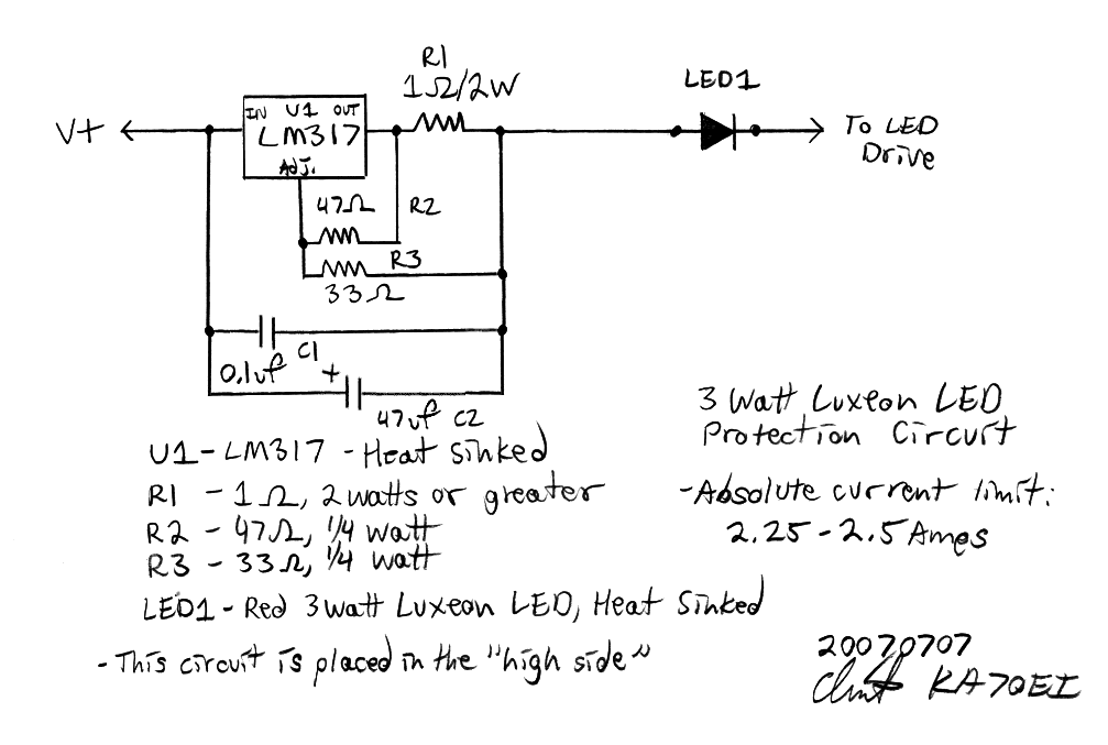
Figure 1 shows such a circuit. This is a modification of the typical LM317-based current source in that R2 and R3 have been added, but its operation is the same:
- As the current increases, a voltage appears across R1.
- When the voltage on the "Adjust" terminal is about 1.245 volts below that of the "Output" terminal, the current is reduced.
While it would have been possible to synthesize such a resistance by paralleling resistors or just using a piece of known-length and gauge of small magnet wire, I decided to construct a circuit that used more common resistor values and Figure 1 is the result. In this case, R1 is set for a slightly higher resistance to effect a higher voltage drop while R2 and R3 divide that voltage such that at 2.25-2.5 amps, the Adjust-to-Output differential is in the 1.245 volt range.
 |
 |
Connected in parallel with this circuit is bypass capacitance. If the LED is modulated with waveforms that contain high frequency components (like those in a PWM circuit, high frequency subcarrier, or video modulation) the bypass capacitance (C1 and C2) allows high frequency components to pass around the LM317 while still offering protection to the LED from a DC current fault. The use of two capacitors is recommended as the 0.1uF capacitor will be transparent to the highest frequency components, while the larger electrolytic will better-pass the lower frequency components. It is recommended that 105C (high temperature) and high-frequency electrolytics (such as the low-ESR types designed for switching power supplies) be used - particularly if the capacitor is exposed to the heat from the LM317.
Total voltage drop of the circuit in Figure 1 at 2.5 amps is around 4.5-5.0 volts. This, in series with a Luxeon III LED would imply that there is a total voltage drop of as much as 7.75-8.25 volts - but this is still enough headroom for many circuits that operate from a 12 volt source - but some circuits may need to be modified. As mentioned before, if R2/R3 are omitted and the Adjust terminal is connected to the load side of R1, the value of R1 can be reduced to an experimentally-derived value in the 0.6 ohm area, reducing the voltage drop at 2.5 amps by a volt or so.
Constructing the circuit:
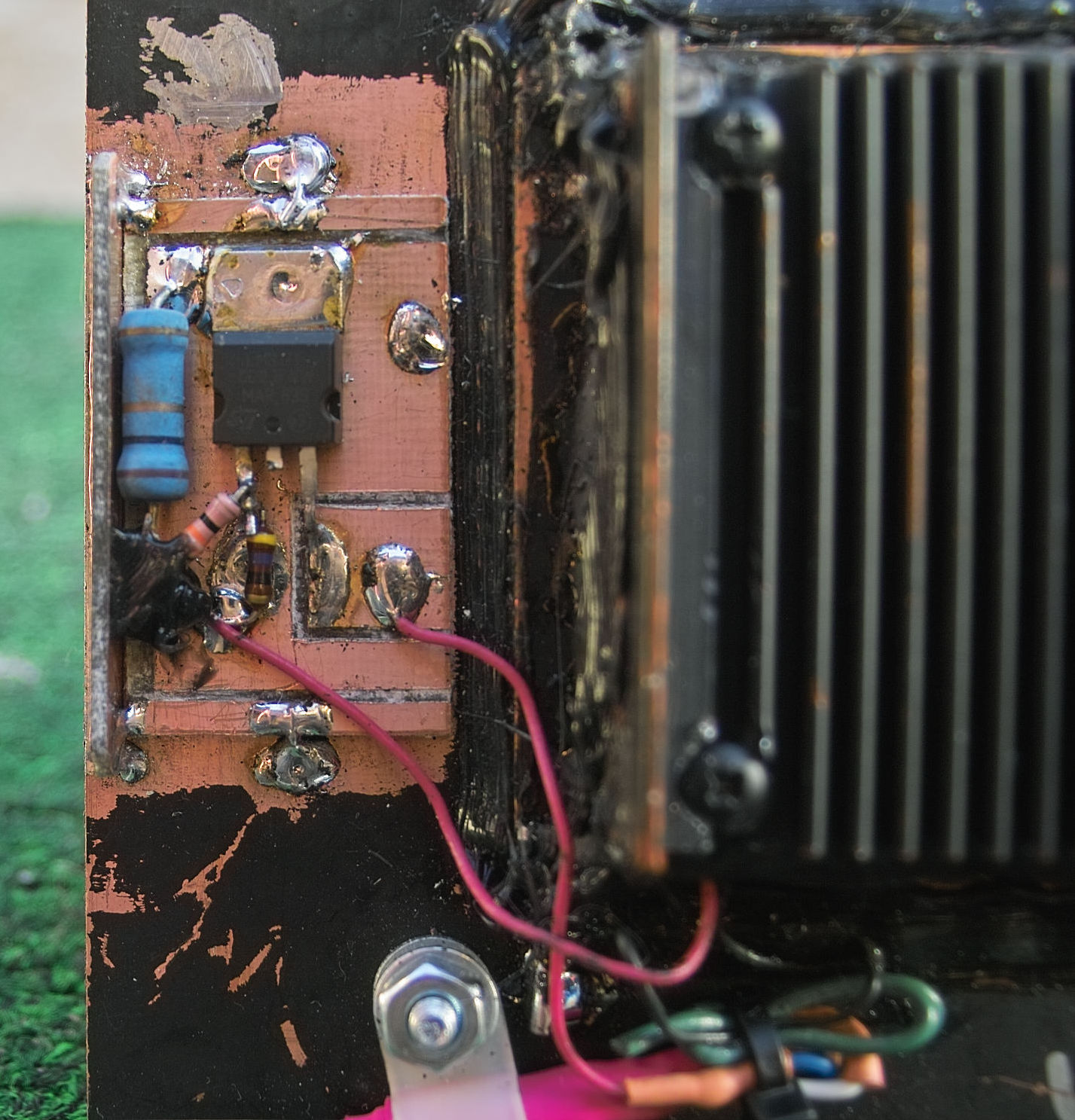
As can be seen from the pictures in Figure 2 this circuit can be constructed in a number of ways. It is essential that the LM317 have at least some heat sinking. In normal operation, the average LED current of a Luxeon III will be about 1 amp, peaking to 2 amps or so at 100% positive modulation. Under these conditions, the LM317 will have to dissipate about 2 watts of heat while R1 will be dissipating around 1 watt.
Even though this is a fairly small amount of heat, it is important that this circuit NOT be mounted on the same heat sink as the Luxeon as a quick check of the Luxeon's specifications will show you that is it warms up, its efficiency drops, so it is best not to add another device that will warm it up! As shown in these pictures, the LM317 is mounted separately from the Luxeon's heat sink - preferably off to the side so that convection will not be likely to cause one heat sink to heat the other.
It worth noting that it is also a good idea not to excessively heat sink the LM317. A good example of this is shown in the bottom picture of Figure 2 where the LM317 is simply soldered to a piece of copper circuit board material. This provides adequate heat sinking for normal operation where the LM317 is dissipating about 2 watts. If a fault develops and, say, a full 12 volts is placed across the LED drive, this will cause the current to exceed the 2.25-2.5 amp threshold and when this happens the voltage drop across the LM317 necessarily increases and this will dramatically increase the amount of heat being dissipated by the LM317. In this state, the current will start to drop as the LM317 gets hot, soon reducing the current to well below the 2.25-2.5 amp threshold. It is under these conditions that a very large heat sink is less-desirable as it would prevent the LM317 from heating up and reducing the operating current.
Operational use:
As mentioned before, there must be enough voltage headroom in the power supply voltage and modulator circuit to accommodate the added voltage drop of this protection circuit. In the modulators that I have built, power MOSFETs are used along with 1 ohm current-sense resistors, adding as much as 2.5 volts of additional drop - but these run will drive the LED to over 2 amps with an 11.5 volt supply - the voltage of a mostly-discharged lead-acid battery.
Under normal conditions this circuit is completely transparent in that other than an addition I*R voltage drop across the sense resistor, there are no effects at all. When the current exceeds the preset threshold, however, the LED drive is clipped at that level and could cause some distortion. A quick look at the schematic will also reveal that I have placed it in the "high" side of the LED supply. This was done in the event that the "low" side of the LED (which, in my case, goes to the modulator) gets shorted to ground: A high-side current limiter will still protect the LED in this case.
Note that because this circuit sits inline, there is no real voltage limit to it aside the voltage differential that would occur under fault conditions when the LM317 is current-limiting. What this means is that if you were to run a string, say, 5 Luxeons in series from a 24-36 volt supply, you could: This circuit would happily protect them all.
Other types of circuits:
 |
When I was deciding how to protect the Luxeon I was considering other types of circuits such as comparators driving MOSFETs or other transistor-based limiter. While these would work - and some have the advantage of having lower voltage drops - none of them were as simple as the LM317-based circuit shown here and some of them require their own supply voltage to operate. This circuit has the advantage of being cheap, simple, and it need only be placed in series with the current flow, not needing a ground or voltage reference.
Why not a fuse?
There is also the obvious question as to why not use a fuse? If you look closely at a Luxeon III emitter (see Figure 3) you'll note that it already has a fuse disguised as a bond wire connecting one of the terminals to the center of the emitter die. If you use an external fuse, it must be one of a lower rating and faster than that bond wire! Clearly, this rules out slow-blow fuses as well as thermistor-type PTC fuses. It is also worth noting that there is quite a difference between the "hold" current of a fuse and the current at which it will blow quickly, and a current at which the fuse will fail over a longer period of time - not to mention a fairly wide range of variability of fuses of the same ratings - even those from the same manufacturer. Finally, if one uses fuses, it is imperative that spares be kept onhand.
Final comments:
Despite the voltage drop which is something that can be worked around in most circuits, usually through a minor change, the described protection circuit works very well to keep peace of mind - and it could prevent the sudden, expensive end of testing should some sort of fault or accident occur that might open up the LED.
Return to the KA7OEI Optical communications Index page.
If you have questions or comments concerning the contents of this page, feel free to contact me using the information at this URL.
Keywords: Lightbeam communications, light beam, lightbeam, laser beam, modulated light, optical communications, through-the-air optical communications, FSO communications, Free-Space Optical communications, LED communications, laser communications, LED, laser, light-emitting diode, lens, fresnel, fresnel lens, photodiode, photomultiplier, PMT, phototransistor, laser tube, laser diode, high power LED, luxeon, cree, phlatlight, lumileds, modulator, detector
This page and contents
copyright 2007-2015. Last update: 20150819