March 31, 2007
 |
 |
 |
On Monday, March 19, I dragged my Optical Transceiver lens assembly into the field for the first time: Having only tested it over very short distances, I wanted to get a "feel" of how bright its beam might be when cast across the Salt Lake valley. On that evening, at about 9:30, I had arranged for several people across the valley to look toward my location to give a report as to what they could see and to judge the brightness of the beam.
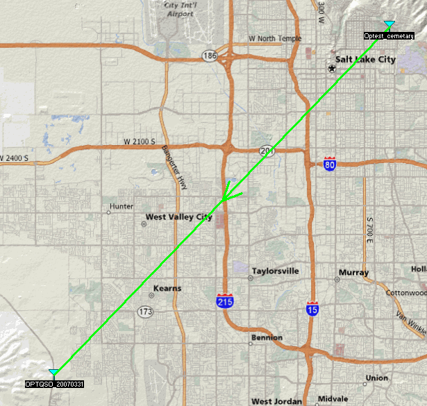
At this point, there was just one optical ("lightbeam") transceiver available, so there was no expectation of being able to make a contact: The only goal was to be seen. I chose a location along the western edge of the Salt Lake valley along Utah Highway 111 (even with 70th south) - a location that is higher in elevation than the existing population centers with no nearby lights. Gordon, K7HFV, was viewing from a location along the north edge of the Salt Lake City cemetery: The cemetery was a good choice as it was devoid of light sources - and because it is close to the mountain, there are few lights "behind" it. The distance? 14.85 miles (23.9 km.)
Initially, Gordon tried to spot my light from a different location, in amongst city lights and other buildings. Being that it was now dark and familiar daylight visual references were now lost, he wasn't quite sure where to look - and I wasn't sure either. Despite waving a laser around, hoping that he would catch a glimpse, he saw nothing, so he went off to find another, darker location.
In the meantime, three other hams were looking for my signal from another part of the valley. One of them, living in an area with fewer streetlights, make himself visible by shining a powerful flashlight in my direction, giving me a precise idea as to where to aim the optical transceiver. Before too long, he could easily see the red Luxeon glow. After a few minutes, I swung the transceiver toward two other hams that lived only a few blocks apart and soon, they, too were able to see the red glow.
By this time, Gordon found the cemetery location - but I had only a general idea as to where that was, and he still wasn't sure where I was. Line-of-sight visibility was soon verified by my shining the laser around in that general direction, providing a visual reference for Gordon. After a few minutes, he, too, could see the red Luxeon glow: He reported that the light was quite bright in comparison with the other city lights and quite distinctive, owing to the fact that it was red.
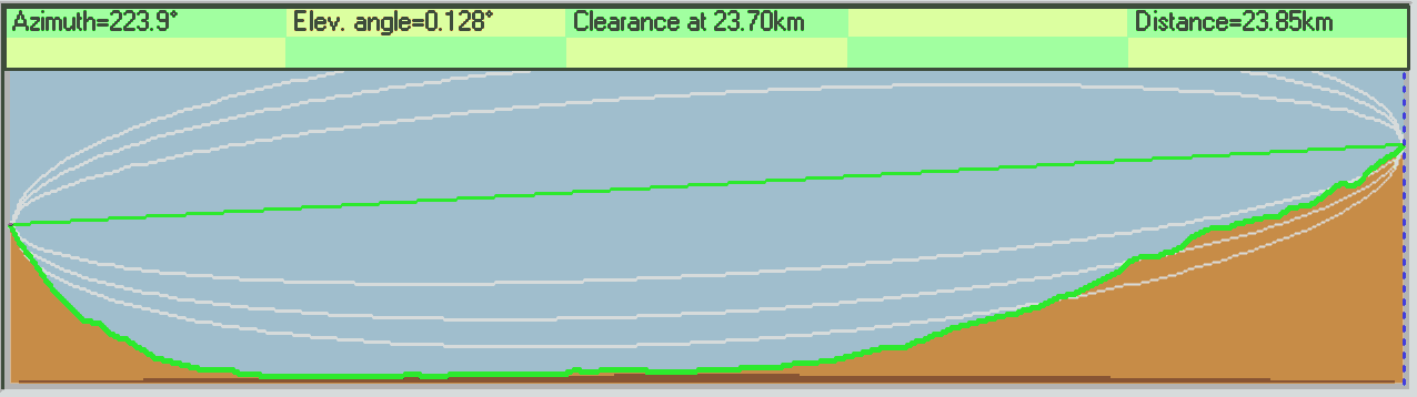
Over the course of the test, it was noted by those that were observing that the amount of scintillation visibly increased as time goes on. Owing to geography (see figure 3 below) the Salt Lake Valley rests in a bowl. This bowl inevitably results in a "temperature inversion" - that is, the bottom part of the valley is cooler than the air above. On this particular night, this inversion inversion was very mild, but was being disturbed by ever-increasing diurnal winds that flow between Salt Lake valley and Utah Valley (immediately to the south) and, in fact, these winds were increasing as time went on. As it turns out, our optical paths were within the boundary layer, resulting in more disturbance than would otherwise be noted.
Encouraged by these results and getting a better "feel" as to what sort of visual magnitude could be expected from the focused 3 watt Luxeon, I decided to construct another enclosure. While I have onhand two larger, high-quality Fresnel lenses, I decided to try an experiment and build a cheaper version using some Fresnel "page magnifier" lenses - the result being shown on the "Cheap Enclosure" web page.
A slight snag:
While I had little doubt that there was enough signal to make a good contact, I decided to perform a minor modification of the receivers used in each enclosure to improve the signal-noise ratio: The installation of a narrowband red filter in front of the detector to reduce effects of urban lighting. Some months ago, I had gone to a local supplier of theatrical equipment and noticed that they had some "swatch" booklets containing a small (1"x2") sample of each of their theatrical gels along with a handy chart showing the spectral response of each. After perusing the "swatch" book and doing some tests using a red Luxeon and the booklet's samples, I settled on a particular gel that I thought looked promising, as it seemed to attenuation the desired light by only about 1dB.
Several days prior to the test, I happened to be at this same supplier and obtained a sheet of the color filter gel that I'd considered - namely the Roscolux "Fire" (#19) - and paid $6.95 for a 20"x24" sheet. This filter material (a graph showing the optical response versus wavelength of this gel may be seen here) looked as though it would be capable of attenuating a signification portion of the stray light from the urban lighting such as the sodium D-line emission at about 590nm (although low-pressure sodium vapor lamps are uncommon) in addition to the strong peak around 559nm, as well as the strong Mercury lines at 579, 546, and 436nm - leaving mostly the broader emissions that fell within the filter's passband. (Note that the photodiode is increasingly less-sensitive at shorter wavelengths, anyway.)
Out of this sheet, I cut two pieces (about 1-1/2" or 4cm square) to put in front of each detector. Because these filters are dye-based, they are not particularly sensitive to the incident angle of light - unlike the more-expensive dielectric filters - so they may be installed at about any point in the optical path.
The first test with this gel was done using the "cheap" enclosure - the one made of the "foam core" posterboard. Because of the receiver is a bare circuit board, I simply taped the piece of color filter gel to the shields that surround the photodiode on two sides and then re-installed it back into the enclosure. Much to my surprise, the entire receiver and enclosure became extremely microphonic and the amplified speaker could not be placed anywhere near the enclosure and it was quite sensitive to room noises in general: In other words, it made a pretty good microphone!
"Hmmm..." I thought. I hadn't noticed this problem before, so I removed the gel and added some dabs of silicone to some of the dead-bug wired components on the receiver assuming that I'd just missed the problem and assuming that the components' movement might be part of the problem, reinstalled the gel, and tried it again: No change - still microphonic.
At this point it occurred to me that the gel had something to do with it: Removing the gel completely restored the operation of the receiver to its previous state - that is, it was only slightly microphonic. Clearly, the vibration of the thin gel was somehow modulating the space around the photodiode: I surmised that because of the relatively large area of the photodiode and the extremely high impedances involved, any slight changes in the nature of that space (such as the slight change in the free-space capacitance) would be translated as audio output.
The interim solution was to form a small cardboard enclosure around the circuit board and use this to space the gel 2 inches or so above the photodiode. While this configuration greatly reduced the microphonic tendencies to the point where it was "tolerable" it was still noticeably more microphonic than it had been without the gel. The optical receiver for the other enclosure was mounted in a shielded case but its microphonics were still noticeably worse after installing the gel: There, too, I used a piece of cardboard to stand the gel away from the photodiode an extra inch or to.
It wasn't until the day after the testing that I finally figured out what had happened: I hadn't thought much about it during the test, but neither Ron, Gordon or I noticed any problems with microphonics and the enclosures. Even with the modification on the "cheap" enclosure, it was still likely that feedback would have resulted if the amplified speaker had been turned up very loud.
 |
 |
It finally dawned on me that the mere handling of the filter gel probably induced a strong electrostatic charge on its surface, causing it to act exactly like an electret microphone. Over the few days between the installation of the gel and the test, this charge had apparently dissipated, greatly reducing or eliminating this effect.
The gear that I used:
I used the heavier wooden Optical Enclosure along with its higher quality rigid Fresnel lenses. It has a 3-watt Luxeon emitter with a current limiter with a high quality glass PCX (PlanoConveX) secondary lens. The optical receiver is the "Version 3" non-feedback optical receiver (operating from a single 9 volt battery) mounted in a completely shielded metal enclosure.
The modulator that I used was a prototype PIC-based PWM circuit that I had built in 2006, but had only recently gotten around to installing in a box. This modulator holds the peak current constant, but it varies the duty cycle of the 20 kHz driving waveform to effect modulation of brightness. In this circuit, the input audio is amplified, lowpass filtered (for alias prevention) and then applied to the A/D input of the PIC that performs (adjustable) audio compression and limiting to minimize the peak-to-average ratio as well as to prevent overmodulation. In addition to audio processing, the PIC can also generate different types of tones that can be used for identification and peaking of the receive signal as well as for analysis of scintillation. One feature of this modulator is the ability to continually adjust LED current from full output all the way down to just a few milliamps while still maintaining 100% modulation. This modulator also has a monitor jack (for use with headphones or audio recorder) to verify operation of the modulator, a built-in microphone, a connector for an external microphone, and a line-in jack for an external audio source such as a computer or digital audio player.
For listening, I used a homebrew LM386-based powered speaker. The optical receiver also has a second output that can be fed to a second audio device, such as a recorder or computer.
On my end I also used two digital audio recorders: An inexpensive ($30) 1GB MP3 player with a built-in microphone was placed on the table with the gear and used to capture ambient audio while a more expensive record-capable MP3 player (with line input) was connected directly to the optical detector in parallel with the speaker amplifier's input: Next time, I'll split the audio channels of this unit so that one will be my transmitted audio and the other will be the received audio.
The gear used by Ron and Gordon:
The Fresnel lens assembly (the "Cheap Enclosure") that Ron, K7RJ and Gordon, K7HFV were using had been assembled by me (with a little help from Gordon) in just one evening. This enclosure uses some very inexpensive "page magnifier" Fresnel lenses that are of fairly low optical quality mounted in 8"x10" picture frames, with the entire box being constructed of "foam core" flat black posterboard. While I'd also constructed a septa from scraps of the foam-core board in the event that the nearby lights would be a problem with the rather poor quality of the Fresnel sheet protector, it turned out not to be required and was never used: It might be interesting to try it later to see how much reduction of unwanted light (as well as the signal) results with its use.
In this enclosure I had installed a 3-watt red Luxeon on a heat sink along with cheap plastic 20mm diameter DCX (Double ConveX) secondary lens and an LM317-based current limiter to protect the LED in the event of a circuit glitch or malfunction. Also installed was the original prototype of the "Version 3" non-feedback optical receiver - a circuit identical to the final version except that it does not have the 3.5 kHz lowpass filter or the high/low gain switch. Even though the optical receiver did not have a lowpass filter, there were no problems with its reception of the PWM signal being emitted from my transmitter.
Immediately after constructing the "cheap" enclosure I built a new, current-linear modulator based on a design that I'd been kicking around in my head: It uses a precision current sink to modulate the LED's current and allows 100% modulation at any desired resting current level. In addition to this, it has a built-in audio compressor to prevent exceeding 100% negative modulation as well as to maximize the peak-to-average ratio of the audio (to enhance intelligibility) as well as a PIC-based audio tone generator that can be used for identification and peaking of the received signal as well as analysis of the amount of scintillation.
For listening, an inexpensive Radio Shack LM386-based amplified speaker was used while the microphone was either the unit built into the modulator or an external computer desk-type or headset-type microphone - whatever was handy at the time. Some recordings were made at this end using a cassette tape recorder with an open microphone.
A real, 2-way test:
 |
 |
On the night of Saturday, March 31, 2007, after meeting with Gordon, and Ron and his wife for dinner, I went to a location along Utah Highway 111 very near where I had been on the 19th (a hundred meters or so north, with more level ground) with my optical transceiver, while Gordon, K7HFV and Ron, K7RJ went back to the Cemetery location that Gordon had scouted out the week before - this time armed with the "Cheap enclosure" and a newly-constructed LED modulator: The distance? 14.91 miles (23.85 km.) The starting time? A bit after 9PM and after local dark.
At Ron and Gordon's end, they parked along a road that paralleled the northern boundary of the Salt Lake City cemetery at an elevation of about 4860 feet (1480 meters) above sea level. Conveniently, there was a stone wall demarcating the cemetery's northern boundary and this appeared to provide a convenient, stable platform for the "Cheap Enclosure."
On my end, I simply pulled a few feet off the highway into a patch of dirt at the crest of a hill, providing a wide panorama of the Salt Lake valley at an elevation of about 5180 feet (1580 meters) above sea level. At this location, the ground was slightly muddy from rainfall a few days past - and this turned out to be pretty convenient. Setting up a portable table with the car between me and road, began to pile equipment onto the table and connecting the gear while Ron and Gordon were doing a similar thing on their end.
After a few minutes, using a 2 meter liaison frequency, I began shining a laser in their direction so that they would have a solid visual reference as to my position to facilitate aiming. Powering up my equipment, I kept an eye open in their direction and it wasn't too long before I spotted flashes of the tell-tale red Luxeon glow as they swung their beam past my location. Using 2 meters, I talked them into a reasonably good aim and then proceeded to point my transceiver in their direction. After only a few moments, they could see my LED and after a few more moments of peaking (and pushing the leg of the table into the mud to fine-tune the elevation setting) I was shining a reasonably bright light in their direction. After a quick re-peaking on their end, using the amplitude of a test tone that I was sending, they were properly aimed toward me. Fortunately, the careful use of alignment targets and laser pointers (as described here) resulted in the peaking of my signal on their receiver being precisely coincident with the brightest signal being transmitted by them.
Audio file: This is a stereo audio file, with the left channel being from a nearby microphone while the right channel is a recording directly from the optical receiver:
Signal quality:
- Initial signal acquisition and greeting: This has a test tone followed by the first voice exchange. (MP3, Time = 51 seconds, 1011kB)
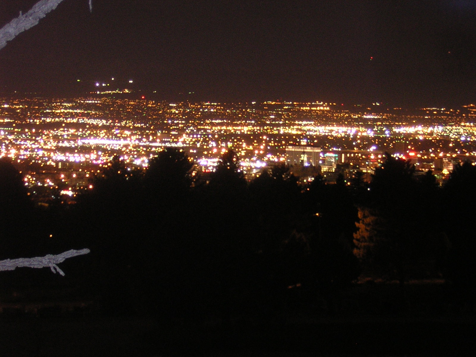
The general quality of the signals was excellent. As can be seen from the pictures in Figure 1, it would seem that Ron and Gordon fared slightly better in this department owing to the fact that I was located in an area that was mostly above all of the city lights. From my vantage point, however, their light was very near those of downtown Salt Lake City and there seemed to be a strong, periodic source of 120 Hz buzzing that had a period of a minute or two: When this source came on, it was quite annoying, although it didn't affect intelligibility of the transmission from Ron and Gordon very much. Presuming that the source of this periodic interference was likely a failing streetlight that was constantly restriking, I looked - but could never spot it.
Because I had made direct-coupled audio recordings onto a digital recorder (48kHz sample rate with 16 bit audio) I could measure relative signal levels and the amount of scintillation present on test tones. This 14.91 mile (23.85 km) optical path is directly over a densely populated metropolitan area, crossing a bowl-shaped valley with a maximum ground clearance of about 740 feet (225 meters.) Because of diurnal breezes the "heat island" effect, and the expected effects of pollution, scintillation is probably worse than it would be were a mountaintop-to-mountaintop path used.
 |
A note about the lenses used:
- The "cheap" enclosure being used by Ron and Gordon had identical
Fresnel lenses on receive and transmit that were about 7.25" by 10.25"
(184x260mm) and have a focal length of
approximately 12.25" (about 310mm) and are extremely thin, flexible
(and inexpensive) vinyl "page magnifier" lenses with fairly high line
pitch (about 0.2mm) with rather poor optical
quality.
- The optics on my end were a pair of identical lenses that are approximately 12-1/2" x 9-7/8" (318mm x 250mm) with a 13" (330mm) focal length. These are rigid, molded lenses that are about 2mm thick and are of good optical quality with rather coarser (0.5mm) line pitch.
Testing with lasers:
Several months ago, Ron had built a pair of laser pointer communicators: These were modulated (at around 40 kHz) using PWM techniques and built on some plug-in prototyping board having been quickly thrown together for the local radio club's "Homebrew night." Being that the detectors already being used for the LEDs were compatible with these lasers, it was a simple matter of aiming them once we had already aligned the LED-based transceivers.
As it turned out that while we knew that aiming with lasers would be tricky, we had no idea exactly how tricky it would be: Many long minutes were spent on 2 meters (or over the LED transmitter) saying things like "weak flash... nothing... nothing... bright flash..." while each of us attempted to aim our lasers at each other. On my end,I was fortunate to be able to plant a tumbleweed into the mud some distance in front of the laser, providing a handy visual reference to get me within the ballpark: Fine-tuning was done with great finesse to finally peak the signal at the other end, relying on the party at the far end for feedback (e.g. "dim... nothing... Bright - Don't touch that!") Ron had a bit more problem pointing his end owing to the lack of a convenient twig or branch to serve as a "sighting stick" but was eventually able to align the laser on several occasions.
There was another problem: Although the laser transceivers were identical, the one Ron was using had had developed a problem in that it would manage about 5% modulation, but above this it would distort terribly. The transceiver on my end started to suffer from a similar problem, but the installation of a fresh 9 volt battery solved it - but there was some initial confusion as to why my transmitted (laser) audio was still somewhat distorted. In testing locally, I determined that the modulator on my end was, in fact, working properly, but that it was the extreme scintillation that was causing the audio distortion. The scintillation was severe enough that even the unmodulated carrier sounded "hissy" as the following two clips demonstrate.
Audio files: These are stereo audio files, with the left channel being from a nearby microphone while the right channel is a recording directly from the optical receiver:
- Dead carrier
with laser - This audio clip is the sound of the unmodulated
laser signal: The "hissing" noise of the scintillation is clearly
audible. (MP3, Time = 17 seconds, 346 kB)
- Modulated carrier with laser - This audio clip includes Ron's voice, but due to technical problems, the modulation depth was only about 5%. (MP3, Time = 7 seconds, 138 kB)
 |
 |
In looking at the top image of Figure 5 you can see the lowpass-filtered 440 Hz waveform. In this segment one can see significant scintillation - but only on the order of 15dB or so: Judging by ear, the the scintillation was far worse than this. In looking at the unfiltered waveform, I could also see that the period of the scintillation was fast enough that the 440 Hz fundamental frequency simply wasn't high enough to show it in detail.
The bottom image of Figure 5 shows the 7th harmonic (at about 3080 Hz) of the 440 Hz test tone. With the higher temporal resolution, the true magnitude of scintillation starts to become apparent: Close-up investigation of the waveform (using a tighter "zoom" of smaller portions of this clip) indicates that there is at least 40dB of scintillation present.
Close-up inspection of the 3080 Hz waveform reveals something else: Not only is the same 12 millisecond (plus subharmonics) period present, but there is evidence of harmonics of this period as well. Unfortunately, the magnitude of these scintillation harmonics is difficult to discern owing to modulation by the original 440 Hz fundamental frequency of the test tone: In the future, more tests will be done with a higher frequency audio tone. It was also interesting to note that when I examined the same segment of the audio recording shown in the bottom image of Figure 5 that had been lowpass filtered, only about 10dB of scintillation was apparent, the true magnitude being masked by the limited bandwidth.
Audio files: These are monaural recordings of the signals from KA7OEI sent to Ron and Gordon via laser. The two clips with the tone contain the segments shown in Figure 5. Note that due to MP3 audio compression, the finer details of the scintillation are lost.
- Lowpass filtered
test tone - This is the recording of the 440 Hz fundamental
frequency, lowpass filtered at about 800 Hz. (MP3, Time = 38
seconds, 224 kB)
- Test
tone - 7th harmonic - The source is the same as the above clip
except that this is the 7th harmonic of the 440 Hz test tone.
With the greater temporal resolution, the true magnitude of the
scintillation becomes apparent. This tone was highpass filtered
at about 2700 Hz. (MP3, Time = 38 seconds, 224 kB)
- Voice recording -
This recording shows the effects of the scintillation on the
voice. The distortion on the signal is believed to be due mostly
to the scintillation, as local testing of the laser's modulation did
not reveal anywhere near this level of distortion. After the
voice ID, there are a few seconds of unmodulated carrier: The
noise you hear is due solely to scintillation. (MP3, Time = 5
seconds, 34 kB)
- It should be pointed out that this is not
really a completely fair comparison to demonstrate the amount of
scintillation of a laser's coherent light verses the noncoherent light
from an LED: The transmitted aperture of
the laser was only a few millimeters across, while the
aperture of the LED was over 7"x10" in size - around 10000 times
larger. A much better (and fairer) comparison would be a test
with equal-sized emitter apertures, and this is something that I hope
to do, eventually. (Note: Later tests were
done to provide a fairer comparison of coherent versus noncoherent
light, see the "Our Second
Optical Test" web page.
- It was noted that the brightness of the LEDs were comparable to the apparent brightness of the lasers, but it was very clear that the lasers "flickered" far more than the LED, almost seeming to go out at times.
- For a better measure of scintillation when using this sort of
laser configuration, a fairly high audio tone is required to obtain
sufficient temporal resolution to be able to being to discern the true
magnitude: I hope to do this on a later test. Later
analysis of scintillation was done using a 4kHz tone, as noted on the
web page about the later testing - see above.
Attenuation test:
Prior to the testing, I did not know what I should expect: Would the city lights overload the detector? How much margin would I have? In order to answer these (and other) questions (and to be prepared in case of overload) I made an "optical attenuator" which was a piece of press board with a lot of holes drilled into it in a grid pattern. This method of attenuation was chosen mostly because I could not find a piece of dark plastic that I could be sure to block the vast majority of the incoming light - especially at Infrared wavelengths where most filters are not rated, but the photodiode is sensitive. The obvious way around this was to do what cameras do: Iris attenuation. It was also important that the aperture of the Fresnel Lens be maintained (to minimize scintillation) despite the attenuation, thus the need for the grid of holes rather than one large hole in the middle of the attenuator.
Audio file: This is a stereo audio file, with the left channel being from a nearby microphone while the right channel is a recording directly from the optical receiver:
- Optical
attenuator test - This audio clip demonstrates the effect of
the attenuator on the signal. Partway through the test the gain
on the receiver was switch to "high" as noted in the audio
commentary. (MP3, 59 seconds, 1154kB)
Careful aiming is important!
While this test ran for about 3 hours, it wasn't until a bit after the 2nd hour (and after the attenuator test) that it finally occurred to me that I hadn't really checked the peaking of my optical transceiver: At the time of initial acquisition, I'd simply aimed my LED via feedback from Ron and Gordon and when they reported seeing it brightly, I left it alone. They then used my generated tone to peak their transceiver - but I never re-checked mine. Up to this point, I was being annoyed by a fairly loud racket caused (apparently) by a constantly-cycling street lamp somewhere in the distance, but after re-peaking the signal, I not only gained another 10dB of signal from Ron and Gordon, but I moved away from that annoying noise source, improving the signal-noise ratio considerably.
Also important - proper focusing and alignment!
Another thing that I noted was that my transmitter and receiver weren't aimed precisely parallel. After getting home, I determined that this was due to the fact that the receiver mounting tube isn't as secure as it should be: For proper receive focus, I had to pull the tube out most of the way and because of this, it would not seat securely and could wobble about, causing the aiming to shift slightly. This problem particularly annoyed me because I was aware of it and even made a new receiver mount, but had never gotten around to installing and adjusting it...
A couple of weeks after the test, I constructed a "Photon Beacon" (a 4060 timer/oscillator with a 500 kHz ceramic resonator and a red LED) and, over a distance of just over 500 feet (about 160 meters) I was able to precisely adjust the receiver focus and aiming and discovered that it had been significantly misadjusted. Proper focusing resulted not only in a gain improvement of at least 10-15dB, but it also improved rejection of off-axis signals. No doubt I would have had much better signal margins had the receiver been properly focused at the time of testing.
I later happened to re-check the receiver focus of the "cheap" enclosure and found that it was within 1dB of optimum, so I didn't do anything other than put more thermoset glue on the box to make everything more stable. I also compared the luminous flux of the "cheap" enclosure with the wooden enclosure and found that it (the "cheap" enclosure) was about 4.2dB lower output. Further testing showed that for receive, the cheap, vinyl Fresnel lenses are significantly inferior in off-axis rejection of other light sources: While the beamwidth of the "peak" response is similar to that of the acrylic Fresnel lenses used in the wooden enclosure, they produce a somewhat "fuzzy" spot - some of which extends several degrees in other directions. Additionally, the somewhat inferior lens material - plus the finer "groove" pitch tends to cause a bit more random light scattering than the more coarse lines on the acrylic lenses in the wooden enclosure.
LED current tests:
After re-peaking, we decided to do some tests to see how much we could reduce the current and still maintain communications. Because both modulators are designed to allow continuously variable current adjustment while still maintaining 100% modulation (based on the resting current) this was a simple matter of turning a potentiometer - and the presence of a test point on the front panel of the modulator made current measurement a simple matter of measuring a voltage in which 1 volt equaled 1 amp. Note: 1 amp of average current equates to 2 amps of peak current at 100% modulation.)
Audio file: This is a stereo audio file, with the left channel being from a nearby microphone while the right channel is a recording directly from the optical receiver:
- LED Current
Reduction tests - This audio clip demonstrates the reduction of
LED current versus the effects on the signal. Note that partway
through the first segment I increased the gain of the audio clip by
20dB (as evidenced by the sudden increase in noise) to compensate for
the reduction in far-end audio - something that I accounted for at the
time by turning up the volume control on the speaker monitor.
This clip has also been edited to remove "dead spaces" between
adjustments. (MP3, Time = 4 minutes and 45 seconds, 5578kB)
As evidenced by the audio clips, one of the major limiting factors was the light pollution present: If there had been a sudden power failure that had blacked out the entire valley, I have no doubt that we could have done better that we did as there would have been no 120Hz-related noise, plus there probably would have been some reduction in "hiss" from the myriad of light sources present.
Miscellaneous observations:
- All of us noted all sorts of weird noises that could be heard when pointing the enclosure at different points around the city ranging from the 120 Hz roar of the power grid (and its harmonics) to odd squeaks, grunts, and clicks. Throughout much of the evening I noted an occasional rhythmic, weak "pop" in the audio that sounded very much like the strobe of a tower beacon - but I could not see anything that seemed to correlate with it.
- In previous testing, I noted that I could simply point the transceiver straight into the air and hear myself via Rayleigh scattering and reflection from airborne dust - a fact (carefully) verified by covering the transmit Fresnel lens and noting that it disappeared, also indicating that this effect wasn't due to leakage between the transmit and receive sides of the enclosure. Testing on a moonless night (after my eyes adjusted to the dark) I could see the beam projecting away from the lens into the distance. During the entire test, I could hear myself (albeit weakly) via this scattering in my own receiver, but since the signal from Ron and Gordon was so strong, the gain on the audio amplifier was low enough that feedback was not a problem. I noted with some amusement that, as large trucks would pass alongside where I was parked and stir up a cloud of dust, my "sidetone" audio would suddenly increase - and then fade back again as the dust settled. Gordon noted that they could hear themselves via scattering at first, but when they tried it again later, they could not. Hmmm...
- Despite the use of the low-quality "page magnifier" lens, the "cheap" optical transceiver seemed to perform about as well as the one using the "good" Fresnel lens. Of course, side-by-side tests would be required to do a direct comparison of performance.
- As mentioned before, about 2 weeks after the test, I had the
opportunity to re-check the focus on the receiver that I used and found
it to be far from optimal: Re-focusing resulted in a 10-15dB
improvement in signal gain and better rejection of off-axis
signals. Had the focus been properly adjusted at the time of the
test, I would have experienced significantly better signals.
Audio file: This is a stereo audio file, with the left channel being from a nearby microphone while the right channel is a recording directly from the optical receiver:
- Final Comments
- This clip has the closing comments just as we were shutting off our
gear and getting ready to go home. (MP3, 56 seconds, 1108kB)
Also, these "armchair" field trials were intended to reveal problems with our equipment as well as give experience with the techniques to align, operate, and optimize it. In no particular order, here are a few things that we learned:
- Stable platform - This was mostly a problem with the "cheap" enclosure. Unfortunately, I neglected to make the bottom flat - something that could have been easily done simply by attaching a few extra scraps of foam core board. This led to a tendency for the enclosure to "rock" back and forth on the stone wall and be extremely difficult to keep it aimed. I didn't have nearly as much trouble as azimuth adjustment on my end was simply a matter of rotating the enclosure while elevation was adjusted simply by pushing the table legs into the mud. Had there not been mud, I was still prepared: I had brought two telephone books that could have been used as adjustable shims, simply by selecting the number of pages to achieve the desired elevation. Ultimately, some means of providing a lightweight tripod-type mount (light enough to be carried up a mountain, but strong enough to be stable) needs to be devised in case a table or flat, stable rock is not readily available.
- Fine-tuning adjustments - Despite the use of
"adjustable mud" I still need to construct a "micrometer-type" of
elevation adjustment for my optical transceiver. As can be seen
from the web
page that describes the enclosure, the lid folds underneath - and
it is to the lid that I would attach the elevation adjustment. It
should go without saying that having had any sort of
fine-tuning adjustment in azimuth and elevation would have been of
tremendous help when aligning the lasers! For later testing,
addition equipment was constructed and the enclosure modified to
provide an easy means of fine-tuning the elevation.
- On/Off tone keying - While the modulators have
built-in tone generators, it is clear that I need to add a means of
using a straight key to allow easy sending of CW: Under poorer
conditions, CW may be copyable while voice is not. (It should go
without saying that weak-signal computer modes would do better still...)
- Audio metering - While the tone is useful in peaking the signal, "better-than-ear" accuracy may be obtained by using an audio meter of some sort. The caveat is that the inevitable scintillation is likely to complicate matters, making the resulting reading bounce around quite a bit, so it is likely that some sort of longer-term averaging will be required.
- Audio recording interface - Perhaps combined with the audio metering should be an interface that mitigates the effects of the wildly differing audio levels that one can expect in the field. This device would likely have both a manual gain control and a slow-acting AGC (as well as a peak limiter) that would prevent longer-term changes in audio level from either overdriving the recorder or being too low to be usable. This recording interface would also provide a means of recording both the transmitted and received audio to the separate (stereo) audio channels as well as allowing loopback to permit the distant party to hear themselves via the entire circuit.
- More laser testing - As mentioned before, it would
be
interesting to do more testing with lasers - especially with the Laser
using the same lens aperture size as the LED. Of course, this
testing would include recordings of tones to measure
scintillation.
Notes about the audio files:
- The left channel was recorded using an inexpensive ($30) MP3 player with a built-in microphone. It was placed on the table near the optical transceiver and simply allowed to run for several hours. Because of the open microphone, it picked up not only my voice, but also the audio from Ron and Gordon's and via the speaker (when I wasn't using headphones) as well as the sounds of passing traffic. Inevitably, the sampling rate of this device was slightly different from that of the recorder used for the other channel, so there is some evidence of delay (a slight echo or "hollowness") in some of the tracks.
- The right channel was from a much higher-quality digital audio recorder connected directly to the audio output of the optical receiver, so it did not normally contain my transmissions, except via acoustic coupling from an open microphone on Ron and Gordon's end and subsequent retransmission. Another source of audio was from the slight return due to reflection in the nearby air from the scattering.
- These audio clips are edited somewhat to remove long spaces of "nothing" and, in some cases, the gain was adjusted as noted to make them more listenable. Also, some of the 120 Hz hum (and its harmonics) was filtered out to avoid overloading the listeners' speakers and amplifiers.
- The recordings supplied by Gordon were originally recorded to
cassette tape using acoustic coupling.
Return to the KA7OEI Optical communications Index page.
If you have questions or comments concerning the contents of this page, feel free to contact me using the information at this URL.
Keywords: Lightbeam communications, light beam, lightbeam, laser beam, modulated light, optical communications, through-the-air optical communications, FSO communications, Free-Space Optical communications, LED communications, laser communications, LED, laser, light-emitting diode, lens, fresnel, fresnel lens, photodiode, photomultiplier, PMT, phototransistor, laser tube, laser diode, high power LED, luxeon, cree, phlatlight, lumileds, modulator, detector
This page and contents copyright
2007. Last update: 20070725