for free-space optical communications
Lasers versus LEDs:
|
Before you
experiment with any laser, here are a
few things that you should know:
|
Readers of this, the modulatedlight.org web site, should be well-aware that it it our contention that for some applications, non-coherent light is preferred over coherent light:
- The atmosphere de-coheres light. Differences in atmospheric density (caused by changes in temperature, humidity - among other things) disrupts the phase-coherent nature of laser light by the time it has traveled a few kilometers through atmosphere, its coherence has already been lost. Because coherence is rapidly lost anyway, there would seem to be little advantage to starting out with it in the first place.
- Coherence can exacerbate scintillation. In the distance that the laser light travels while still being somewhat coherent, the atmospheric variations - the same ones that cause loss of coherence - result in constructive and destructive effects on the light which causes random fluctuations in brightness referred to as scintillation and these variations can disrupt information being conveyed on the light. See the Comparison of Coherent and Noncoherent Light web page for a demonstration of the effects of atmospheric propagation on these types of light.
- It is difficult to collimate coherent light to a large
diameter. When dealing with coherent light, it
is necessary to use very accurate "diffraction-limited"
optics - those that are accurate to 1/4 wavelength or better
- to minimize scattering and loss by those lenses. As
the diameter (and size) of these components increase, so
does the weight and cost - not to mention the practicality
of their use. It is desirable to use large-diameter
beams to minimize scintillation and as distances increase,
so does the preferred beam diameter.
A note about the techniques and equipment described on this page:
For the purposes of this web page we are describing only the hobbyist/experimental use of lasers to convey voice or low-speed digital information. Other aspects of laser experimentation such as holography, range-finding and atmospheric profiling (to name but a few) aren't covered.
The goals described here (e.g. long-distance laser-to-laser communications at audio-frequency bandwidths) can also be achieved through the use of lab-quality lasers, precision optics, specialized detectors, and/or precise aiming devices such as special-purpose tripods, detector mounts, telescopes or survey equipment. If you own or have access to such equipment, by all means - feel free to use it!
Note, however, that this page is specifically directed toward those who wish to perform these sorts of experiments using materials and equipment that would likely to be available to a hobbyist with a limited budget. Considerable efforts have been made to describe simple and effective techniques and high-performance equipment that could reasonably be replicated by anyone with the patience and skill to do so.
Whatever you do, be safe!
Examples of laser-pointer communications systems:
Low-power, inexpensive red laser pointers are ubiquitous these days which make them nearly ideal devices with which one can experiment while their low power level makes them fairly safe to use. Even the cheapest pointers have built-in lenses that produce reasonably well-collimated beams - albeit with source diameters of only a few millimeters - that are capable of being seen over quite a distance with the naked eye - over 100km under good conditions!
For voice operations, most inexpensive laser pointers are very easy to amplitude-modulate using PWM techniques and an example of a basic laser-based PWM system can be seen in Figure 1. This circuit, designed by Ron, K7RJ, was intended to be as simple as possible to demonstrate the use of such techniques to modulate voice onto a laser pointer using readily-available components - and it is this very same laser pointer that can be seen in Figures 4a and 4b below. Also on the schematic is a very basic photodiode-based optical receiver, but because the intent of the project was that of demonstration and to test the modulator itself, no effort was made to maximize sensitivity any more than necessary to achieve a very short-range (up to 100 meters or so) communications range.
 |
 |
 |
 |
A somewhat more-complicated PWM circuit is that described in the article "A Simpler Pulse-Width Modulators for LEDs and whatnot". This modulator includes the ability to generate various test tones which are very helpful when it comes to setting up any sort of optical communications system - whether they are LED or laser-based.
If you don't have the desire to build your own system from scratch there are a number of kits available, including the Ramsey LBC6K Laser Communicator kit. (Note: Ramsey Electronics is no longer in the kit business, but some kits may still be found.) This particular kit consisted of a pulse-width modulated laser pointer and a simple optical receiver consisting of a phototransistor and audio amplifier. The "transmit" performance has been reported to be "adequate" for a laser pointer, although it's been recommended that a switch-selectable "manual" gain control (potentiometer) be added to its circuit to supplement the built-in "audio AGC".
Again, the "receive" portions of the Ramsey kit and that of the circuit shown in Figure 1 aren't really suitable for distances longer than several hundred meters - and for several reasons:
- The use of a phototransistor. While cheap and easy to use, phototransistors (as was used in the Ramsey kit) are not the best choice when it comes to good receiver performance - although the sensitivity of the Ramsey kit overall was better than the much-simpler circuit depicted in Figure 1. Not only are phototransistors relatively slow, but under very low-light conditions their own noise contribution tends to mask the weak photon-induced signals. In a simple demonstration circuit where highest performance is not the goal their inherent self-amplification make them reasonable choices when simplicity is of greater importance.
- The lack of low-noise, high-gain amplification. The circuit in Figure 1a wasn't really designed for either low noise or high sensitivity and it simply cannot make full use of the weakest signals that might be coming from the detector. Similarly, the circuit that was used in the Ramsey LBC6K - while significantly better than that circuit in Figure 1a - was not optimized for the best performance, either.
- No additional optics are used. Phototransistor or photodiodes by themselves have very small photo-active areas and because of this they can only intercept relatively few of the photons from the laser. While a brief reference is made in the Ramsey manual to add a lens, the basic kit does not include them and the instructions give no guidance as to their selection or use. Lenses are the best way to noiselessly add considerable receiver gain over the "bare" phototransistor and they have the advantage of limiting the field-of-view of the receiver to prevent off-axis light sources from degrading receiver performance: Even the addition of a small "magnifying glass" lens can make a tremendous improvement!
- "A Highly-Sensitive Optical Receiver Optimized for Speech Bandwidth" - This describes a field-proven circuit - having been replicated by many others - that offers excellent sensitivity through 2-3 kHz - a bandwidth suitable for voice and low-speed digital communications and has been successfully used for subcarrier (20-30 kHz) operations from the "flat" output as well.
- "An
Optical Enclosure - cheap version" - This
page describes an optical system constructed from
"foam-core" paperboard and using inexpensive "page
magnifier" Fresnel
lenses. Despite its being cheap and
lightweight, it has been proven in the field to be fairly
rugged and capable of good performance, having been used to
receive optical signals over a distance greater than
172km (107 miles.) This page includes
links to yet higher-performance Fresnel-based lens
assemblies.
In addition to hand-held laser pointers, suitable low-power laser modules may be found in tools such as levels and often in give-away promotional items. While a pen-shaped laser pointer may be easier to modify and re-mount, it should be practical to (carefully!) extract and re-mount the laser modules from these other devices as well.
Note that all laser pointers consist of more than just a switch with a connection to a battery: There will be a simple circuit to limit laser current - usually on a small circuit board attached to the body of the laser module in some way. With the cheaper laser pointers this circuit may consist of one or two transistors with a few other passive components but some of the very cheapest pointers use just a resistor for limiting current! Whatever form this circuit takes it's a good idea to document its connections and its original power requirements to preserve and use it later on.
 |
If one is using a cheap laser pointer there are several ways to mount it. In Figure 1, the front portion of a laser pointer was removed from the rest of its body, carefully noting where the original battery connections went. In most (if not all) cases, a cheap, red laser pointer has the positive side of the battery connected to the case - and the unit shown in Figure 1 was no exception! Because of this, it is recommended that the laser module be mounted in a plastic case so that it may be electrically isolated from the negative "ground" connection of other circuits.
Another example of a laser pointer being mounted is that shown in Figure 2 (to the right). In this case, I couldn't easily see how to remove the laser module from the pointer's body without some possibility of destroying it so I simply decided to use it as-is and fashioned a "fake battery" to make the necessary power connections. I found a wooden dowel that was about the same diameter as the AAA-type cells originally used to power the laser pointer and, with a saw, cut a groove along its length and into that groove was laid a wire that I soldered to a small screw at the end of the dowel to make the negative power connection.
Around the end of the dowel opposite the screw I wrapped some copper foil tape to make a snug fit when screwed into the original threads at the end of the barrel of the laser pointer and to this foil a piece of wire was soldered for the positive power connection. The dowel assembly was then put into the laser pointer simulating the pair of AAA cells with the screw making contact with the spring inside the laser and taped into place. Finally, the laser's "on" button was simply taped down and the laser pointer itself was attached (using thermoset glue) to a small plastic box that contained the simple electronics to regulate the voltage applied to the laser as well as electrically isolating the positive pointer body from everything else. This same laser pointer module appears in Figure 2, 3 and in Figures 4c-f, below.
Because laser pointers typically run from a pair of Alkaline cells or a lithium coin cell, their nominal voltage is around 3.0 volts - although this can vary a bit. The circuit shown in Figure 1a (above) can be used to drive a laser pointer, as can the circuit shown in Figure 2b on the "Simple PWM Circuit" page.
Note:
- It is not recommended that you use a raw "laser diode module" of the sort often found in electronics parts catalogs unless you know exactly what you are doing!
These are often more
expensive (in the $15-$100 range) and often do not
have the necessary current-regulation circuitry. If
you have one of these, I would recommend that you set it
aside and use a cheap laser pointer instead!
Important notes about modulation of laser pointers:
Do not attempt to modulate a laser diode by varying the voltage!
Laser diodes, like plain, ordinary diodes, have voltage/current curves that can be extremely steep and vary with temperature and even seemingly-identical devices from the same manufacturer can have significantly different operating characteristics. Like other semiconductor diodes, a laser diode will not seem to draw current at very low voltage until they hit the voltage at which start to conduct, at which point the amount of current that will flow will go up more-or-less exponentially with respect to voltage: The difference between a laser being "off" and being destroyed by too much current may be only a few 10's of millivolts and it is for this reason that all laser diodes have some sort of current regulation scheme incorporated within their operating circuitry.
As mentioned above, most "cheap" red laser pointers have very rudimentary current regulation circuits - some of them being as simple as just a single resistor. In these cheaper laser pointers, there are few components (such as capacitors) contained in the regulation circuitry that will significantly affect the ability of the laser diode from being turned on/off quickly as needed for PWM, FM or high-speed data - even into the megahertz region.
Ironically, some of the more expensive laser modules do contain more-sophisticated circuits used to regulate and protect the laser and it is often the case that these cannot be so easily modulated owing to the inability of the circuit to respond to being turned on/off rapidly. Attempts to so-modulate such a laser may, at best, not work very well and at worst, confound the circuits' operations and expose the fragile laser diode to higher-than-intended currents and damage or destroy it. Many "non-red" lasers (e.g. yellow, green, blue, blue/violet) - as well as higher-power devices of any color - fall into this category.
In other words, Cheaper may be better! It is recommended that you start out with the cheapest red laser pointer that you can find (and buy several!) and that way, if you accidentally destroy it, you won't be out much money!
In addition to PWM, it is common to find schemes that modulate the laser current directly. While this method of modulating a laser is possible, it has several practical difficulties - mostly relating to the problem of not knowing exactly how much you can modulate the diode. For example:
- If the diode current goes too low, it stops lasing. With too-little current, lasing stops and the laser operates more like a standard LED.
- If it goes too high, it will also stop lasing - permanently!
Even an extremely brief pulse of excess current can destroy
a laser diode instantly! Any system that modulates a
laser by varying the current should have a "hard" limit to
set the maximum amount of laser current from, say, voice
peaks, "clicks" caused by powering up/down the gear or
transients from connecting it to another signal source such
a s a portable player or computer.
In short, the use of PWM sidesteps most of these problems as the laser is never exposed to excess current as it is simply switched on and off to "simulate" modulation of the beam's brightness.
In other words, the safest way to modulate a laser diode is via PWM!
For practical information about the inner-workings of lasers, laser pointers and laser safety, see Sam's Laser FAQ.
What about FM?
At this point it should be noted that thus far we have discussed in depth only schemes in which the information being conveyed via laser with amplitude modulation of a "baseband" signal rather than some sort of discrete, modulated carrier that is, itself being modulated that is what carries the intelligence. Over the years a number of other schemes have been described in various articles, many of which utilize FM subcarriers to convey voice and/or data. (Note: Even the FM carrier is represented via amplitude modulation since we are using radiometric detection rather than attemptiing to "modulate" the optical signal by varying the wavelength of the light itself!)
The use of FM (frequency modulation) has its merits:
- Noise rejection. The primary advantage of frequency modulation is that its detection scheme inherently rejects noise - as long as the received signal is sufficiently stronger than the noise sources that are inevitably present. Because the information is conveyed as a varying frequency rather than a change in amplitude, the detector can "limit" the received signal - that is, convert it to a constant-amplitude signal in the process of detection and demodulation. With sufficiently-strong signals the received audio will be free of noise from various sources as well as free of the amplitude variations that result from scintillation. In other words, an FM-based system can sound really good - but only if signals are strong enough.
- High carrier frequency. The modulated carrier
frequency of an FM-based system is typically above the
hearing range, placing it well above the frequency band in
which "hum" from city lights (and the harmonics) is
heard. Since there is little energy from these
potentially-interfering sources in the passband of a
properly-designed receiver operating at these "ultrasonic"
frequencies, further rejection of potentially-interfering
noise sources is afforded.
- Complexity. A disadvantage of frequency
modulation is that the receive system is significantly more
complex. To detect it, you must first build an AM
optical receiver and then feed the signal from it to
an FM demodulator of some sort to recover any audio.
If a computer is available, one may use a DSP program such
as DL4YHF's Spectrum Lab ("Google"
it!) to both modulate and demodulate signals - Contact me using the
information at the bottom of the page if you need more
information.
- Reduced system sensitivity. The biggest "hit" comes from the fact that out of necessity, relatively high frequencies - those significantly above the speech range - are used. Because of the nature of detectors such as phototransistors and photodiodes it is extremely difficult to achieve both good ultimate sensitivity and high frequency response, as one must be traded for the other. As it turns out - unless you were to use more-exotic detectors (such as photomultipliers or avalanche photodiodes) - you may lose 20-40dB of detector sensitivity at the necessarily-high frequencies required for FM subcarriers in comparison with a simple "amplitude modulated" system that uses pulse-width (or current modulation) and an "AM" type detector.
Several FM-based systems may be found in published sources as well as elsewhere on the web - see the link to Max Carter's page below - and one was described in the CQ Magazine "Math's Notes" columns in February and March, 2010. Since I have not experimented with a wide variety of these circuits, I don't have a particular recommendation of one over the other although Max Carter's circuits appear to be well thought-out and generally representative of the one of the better ways to accomplish the goal.
Other subcarrier schemes - SSB:
Over the past several years, the U.K. optical experimenters have successfully use SSB (Single SideBand) techniques on subcarriers to sidestep the problem with interference from the hum of mains-powered city lights and their harmonics. Converting from 80 meter (3.58 MHz) to/from about 25 kHz, SSB provides both narrower bandwidth, more voice transmission with a given amount of power and lower signal thresholds than those available from the FM schemes mentioned above. With such a system significant weak-signal performance may be had when compared to an FM-based system and line-of-sight ranges in the 10's of kilometers can be easily attained!
Unlike FM, the use of SSB requires a linear modulator which is very easy to manage with LEDs but as noted above, this is a bit of a challenge with laser diodes. The recommended way to do this would be to simply use a PWM scheme with the switching frequency being significantly higher (say, 3x or more) than the SSB "carrier" frequency using a circuit like that depicted in Figure 1, perhaps using a faster op amp than the 741 depicted to handle the subcarrier frequency: For a 25 kHz subcarrier frequency, a PWM frequency in the 80-120 kHz range would be appropriate.
It is worth noting that with SSB, it is necessary to transmit only one half of the RF cycle so the voltage on pin 3 of the 741 may be made variable (using a potentiometer in the 10k-100k range) and adjusting it so that the LED just illuminated when there is no audio.
As with FM, one may use a computer running DSP software to modulate/demodulate SSB: Contact me using the information at the bottom of the page if you need more information.
If you are starting out, I'd STRONGLY recommend that you begin with a simple AM modulator/demodulator scheme and get that working before using a subcarrier scheme of some sort - especially since you'll likely be able to use the same transmit/receive gear anyway with little modification!
How to set up a laser-pointer communications system over very short distances
Before you go out into the "field" it is strongly recommended that you set up a laser communications system over a very short distance - say, across a yard or field that spans a distance of no more than a few hundred meters. When you plan such a test, the area should be selected that the beam cannot find its way onto a roadway or across a nearby airport either as the beam traverses to the distant end or as it goes past the distant end as the distraction caused by even a very low-power and otherwise "harmless" laser can still be dangerous! Remember: There may be a road or airport beyond your test range into which your laser beam can spill!
At these short distances it is possible for the person pointing the laser to see the distant end and the "spot" produced by the laser hitting the target. It should go without saying that being able to see the spot produced by your transmitter greatly simplifies the aiming process - and it also goes a long way toward getting the "feel" for how your equipment will work. It will also reinforce the realization that many people who go out into the field to attempt laser-pointer communications underestimate the practical difficulties involved!
Even at such short distances it is highly recommended that you have assistants helping you along with a 2-way communications system if you don't want your voice to become hoarse from yelling. If both parties are radio amateurs, simplex radio communication is a natural, otherwise inexpensive FRS-type radios may be used to communicate back-and-forth. Finally, one could also use cellular ("mobile") telephones to communicate if you don't mind burning up your airtime minutes and running down your batteries!
The use of cell phones do have a distinctive disadvantage: Because they are digital, they have a rather obvious end-to-end delay that becomes increasingly apparent when you are trying to do "real-time" pointing. Hearing the sound of your beam going past the receive end's detector by listening to its speaker via the telephone will be slightly delayed (up to several hundred milliseconds) and this delay can make aiming awkward. Also, being digital, a tremendous amount of "lossy" audio compression causes those brief tones and background noises (such as those emanating from your optical receiver) to "confuse" the audio compression, often resulting in what you are hearing over the telephone sounding very different from what you would have heard directly from the receiver! (If you have ever heard what "music-on-hold" sounds like via your phone, you have already heard how badly the digital compression can mangle common, everyday sounds!)
While applicable to only fairly short distances, it is strongly recommended that one surrounds the target with reflective tape and/or inexpensive bicycle/yard reflectors. Because of the "corner cube" construction of these many of these reflective devices, they will readily light up when your laser hits them making it much easier to find the distant target in the dark.
Even at such short distances it becomes very apparent how "touchy" the aiming of a laser pointer really is and one of the first things that is discovered is how useless a typical photographic tripod can be as a means of aiming a laser!
Comments:
- There are certain types of tripods (such as those used for motion picture production or survey equipment) that may be suitable for these purposes, but these are likely to be specialized, heavy and expensive devices and not the sort of things that the average person is likely to have on-hand.
- Remember:
The intent here is to describe a system that can be
assembled using components that are inexpensive and readily
available and/or constructed at home.
Why aren't standard tripods very good for aiming lasers?
- A standard photographic tripod is not a precision pointing device. When pointing a camera, you simply aim up/down, left/right as needed, looking through the viewfinder. Almost all tripods have some degree of "backlash" - that is, the tendency for the tripod to move backwards slightly once you take your hand off it. Since this amount of backlash is usually less than a degree or two, and since there is usually no reason to try to aim a camera with such precision, this isn't really a problem for the photographer. When trying to point a laser, even a fraction of a degree of backlash is too much! Ironically, the cheap tripods that don't have features like a "fluid head" are slightly better in this respect as the viscous fluid is one of the aspects of a tripod that can greatly contribute to backlash! (General "flimsiness" contributes to backlash as well, but this is generally quite manageable on a reasonably well-built - but inexpensive - tripod.)
- There are no means by which minute, repeatable
adjustments may be made. When you use a tripod,
one simply moves it back and forth or up and down to point
the camera and instantly seeing the results through the
viewfinder. When doing so, one has little sense of
exactly how much one is moving it,
particularly if you can't easily see where the laser is
being pointed in the dark! For laser work, having a
sense of how far, exactly, the pointing has been moved is
important if you are trying to scan back and forth several
degrees while making minute adjustments to the
elevation. Not only is it difficult to know exactly
how far to the left and right you have moved each time, it
is arguably more difficult to adjust the elevation
(up and down) by a known amount with a tripod as all you can
do is loosen the elevation's lock screw, make a guess on how
much you have moved it, and re-tighten it.
The above problems are difficult enough to deal with when you are attempting to set up over very short distances and are able to see what you are aiming at, but you don't need increase the distance very much before you can't see your spot reflecting off the far end and have to rely exclusively on feedback from the distant end in your aiming!
How to aim your laser pointer with precision
For longer distances over which you cannot see the terminus of your own beam, you will require some sort of feedback from the other end to assist in aiming the laser and at the very least, this can come from observers who are reporting what they are seeing. If you are really serious about this, it is possible to use an "electronic" aiming aid as will be discussed later.
This topic of precisely pointing the laser could be the subject of several web pages by itself, but in the interest of brevity, we'll cover only two methods:
- Using a telescope/mount, and
- Using a home-built device mounted to a suitable photographic tripod.
While there are many other possible methods of precisely pointing a laser such as using a theodolite or transit - especially one that may, itself, contain a laser that could be modulated - we are concentrating only on those methods that are likely to be accessible to the average experimenter and can be done with little cost.Use a telescope mount:
Many "inexpensive" telescopes (i.e. those that can be had as new for $300 or less) have 2-axis mounts - either "Az/El" (left/right and up/down) or a so-called "Equatorial mount" - the latter often incorporating a "star drive" motor (which we wouldn't be using in our application) to track the apparent motion of celestial objects as the Earth rotates. (It is worth noting that typical Dobsonian telescopes have neither Az or El adjustment screws and rely instead on friction pads to keep the telescope stable and as with a typical tripod, it can be difficult to make precise, repeatable up/down and left/right motions.
 |
Many of these same astronomical telescopes, such as the one shown in Figure 3, also have a 1/4-20 screw mount intended for attaching a camera and one could also use this same mount to attach a suitably-packaged laser pointer. If you own such a telescope - but it does not already have an accessory/camera mount on it - it may be possible to add one, possibly by using straps, hose clamps or stretch bands to attach the pointer.
Such telescopes could be considered "Laser Ready" if they have a knob or gear that will adjust each "axis" independently and in a repeatable manner - that is, one can "scan" the distant end, making systematic azimuthal sweeps while making incremental adjustments to the elevation. If the distant end spots the beam as it flashes past it is then a simple matter of repeating the motion that caused that flash, backing up and re-tweaking the axes to optimize pointing. To be sure, an Equatorial mount telescope doesn't provide true Az/El adjustments, but both axes are still easily and precisely adjustable in a repeatable manner.
Using a telescope/mount has another obvious advantage: It includes a telescope as well as a wider-angle finder scope! If one is careful, it is possible to align the laser pointer in parallel with the telescope and using a visual cue from the distant end (such as a spotlight, car headlights - or even the other end's laser) to provide approximate pointing of the laser reducing the uncertainty of the aiming of the laser to get you "closer."
One disadvantage of a telescope - even one on a sturdy mount - is that it can sometimes "bounce" as the wind hits its fairly large surface area. Such movement - even if slight - can cause the laser's beam to move rapidly on/off point at the far end, disrupting communication.
Another disadvantage of a suitable telescope/mount is that fewer people own these than, say, a reasonably-sturdy photographic tripod. Even though a suitable telescope/tripod can be had for only a few hundred dollars new or used, it is understandable that many people would not wish to make such an investment! Finally, an 8" telescope and its required accessories takes up quite a bit of space in a vehicle!
Using a tripod:
What if you don't have such a telescope?
As mentioned before, standard photographic or video tripods by themselves aren't particularly useful in the precise pointing of a laser pointer. They can, however, be used as a stable platform for a device that may be used for aligning a laser.
In our earliest experiments we attempted to use standard tripods by themselves as mounts for laser pointers - but with mixed success. Over the course of several evenings, many hours were spent in frustration trying to point our lasers at each other, often getting only a few tantalizing flashes from the far end. The problem was that reporting of the flashes by the observer at the distant end was necessarily delayed by the comparatively slow reaction time of the viewer, with the report being made after seeing a flash.
Upon having a report of the distant end seeing the flash, the person pointing the laser pointer (using a tripod) attempted to repeat the maneuver that resulted in that flash but with the laser's narrow beam, doing so was, at best, hit and miss and attempts at making very small changes in pointing often resulted in overshoot or backlash with the end result being that the laser was still off-point. Of particular difficulty was the adjustment of the elevation of the tripod: It was extremely difficult to move the laser up and down without also affecting the azimuth at least slightly. If, by chance we were able to see the beam, there was the inevitable temptation to "tweak" it slightly to achieve the same brightness observed in previous, brief flashes but between the flexure of the tripod, the viscosity of the fluid head, and the effects of static friction of the parts of the tripod such minute adjustments often failed, causing the beam to be lost entirely!
After a bit of this nonsense I simply resorted to using my 8" Celestron reflector telescope's camera mount for the laser pointer. While it worked very well, it wasn't particularly convenient to haul around and set up this rather large, fragile and expensive device and I really couldn't expect that everyone who wanted to participate in such activities also have to get a suitable telescope just to point a laser!
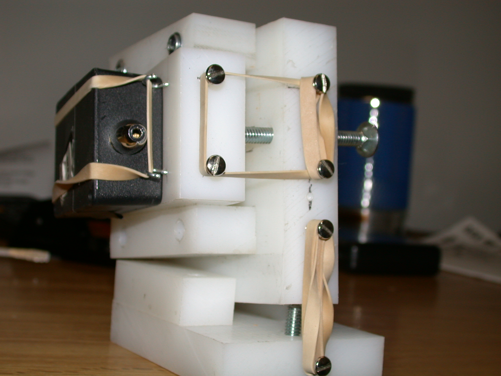
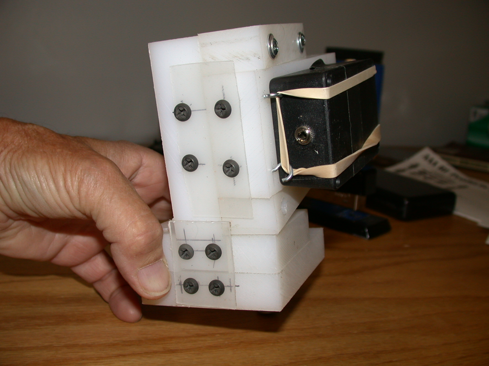
After some discussion with Ron, K7RJ about the construction of a device that could be attached to a standard tripod he decided to build something that could provide the precision and repeatability needed to successfully aim a laser pointer. The results of his work may be seen in Figures 4a-f - a device that we affectionately (and erroneously) refer to as the "Vernier Pointy-thingie."
Which types of tripods are usable with this pointing device? The very light-weight tripods intended for small point-and-shoot cameras aren't generally suitable as they are typically too flimsy. Very short "table-top" type tripods will work - provided that they can be placed on a very solid surface such as the ground or a stone or concrete wall, but placing a tripod on a vehicle is not recommended as they tend to move or settle as gear (and people) are loaded/unloaded. If someone leans against the vehicle - or if there is even slight wind - the vehicle can also move, knocking the laser off-point.
Somewhat "heavier" tripods such as those intended to hold a camcorder or a full-size SLR-type or medium-format camera are generally suitable. In other words: If the "new" cost of the tripod is at least $70-$100, there is a good chance that it will be "good enough." The tripod shown in figures 4c-4f is an inexpensive ($35-$50) "video" tripod that has been used several times for laser communications and has been found to perform quite well.
 |
 |
 |
 |
 |
 |
This device was so-called because we didn't know what else to call it at the time it was conceived: Even though there's no "Vernier" involved, the name is meant to imply a degree of precision and repeatability with respect to the device's operation. We'll refer to it simply as the "Pointing device" elsewhere on this page.
As can be seen from the pictures in Figure 4, this device attaches to a standard photographic tripod and allows fine, repeatable adjustments to both the azimuth and elevation of the laser pointer.
Ron threw the first version of this pointing device together in the late evening/early morning before a planned outing and it was constructed largely from scraps of high-density polyethylene ("HDPE") plastic obtained from the surplus bin of a local distributor - but this material could have been cut from, say, an inexpensive kitchen cutting board. HDPE has an advantage when it comes to moving parts in that it is very slippery and has reasonably low dynamic and static friction.
With specific goals in mind, the design of this device was very straightforward:
- The ability to provide fine adjustment. It should be possible to make even minute adjustments to the azimuth or elevation.
- The ability to make repeatable adjustments. This is, perhaps, one of the most important aspects of this type of device. If you do something that results in the other end briefly seeing the laser, you want to be able to repeat that motion during your efforts to aim it!
- Adaptable mounting of the laser pointer. As can be seen from the pictures, our two laser pointer modules are mounted in very different ways. If we rebuild/improve our laser pointers using different packages, we want to be able to re-use the same mount in the future.
- Stability. Once we make an adjustment, we
expect it to stay!
Mechanical layout:
The assembly consists of three main parts:
- The base plate. This is the piece that attaches to the tripod using standard 1/4"-20 threads. Into it, a threaded rod is installed that pushes the rest of the assembly up to raise the elevation. In practice, one would first "raise" ("pre-set") the elevation a few degrees and from there, be able to move it up and down when scanning.
- The elevation plate. Attached to the base is the "elevation plate" and it is this piece that is pushed up by the screw in the base plate to move it up and down to adjust the elevation of the laser - and it also carries the azimuth plate. It is in the elevation plate that the azimuth-adjust screw is mounted.
- The azimuth plate. Being attached to the
elevation plate, this portion - which includes the laser -
goes up and down. The azimuth screw pushes this plate
away from the elevation plate to provide a degree of
side-to-side movement. As with the elevation, one
would "pre-set" the azimuth outwards a few degrees to allow
both left and right motion.
Guide blocks:
Take a look at Figures 4a and 4c and notice the two blocks on the base plate: These two blocks, attached to the bottom piece, prevent side-to-side motion of the rest of the assembly.
When designing this device, one of the goals was to maintain orthogonality and independence of adjustments - that is, as much as practical the adjustment of the elevation was to affect only the elevation, and likewise for the azimuth. The hinges, which, themselves, also have flex or side-play, would not be enough on their own to prevent side-motion as the elevation was raised up and down - particularly since the weight of the upper piece (which includes the laser) wasn't symmetrical about the axis.
Taking another look at Figure 4a and 4c note that there are similar "guide blocks" above and below the piece to which the laser is mounted. These prevent the laser's pointing from sagging as the azimuth is adjusted "outward" or even over time as the plastic slowly deforms under the forces exerted on it - particularly as the laser is moved "outward" and away from the main block, increasing the leverage. Because these guide blocks are made from polyethylene, there is little friction, but that also means that it is not possible to glue them together. For this reason, all of the pieces comprising the pointing device are screwed together.
Hinges:
In looking at Figures 4b and 4d you can see that the hinges are constructed using thinner pieces of flexible plastic - also polyethylene - taken from a food container.
Why use pieces of plastic instead of real metal hinges? Partly, this was done because the plastic was cheap and on-hand at the moment of construction and suitable metal hinges weren't. In retrospect, it could be argued that the plastic hinges - especially in conjunction with the guides - have little "sideplay" which helps to keep the adjustments both smooth and repeatable. When the second unit was constructed, it was simply a duplicate of the first, taking into account improvements made to the prototype after having been used in the field. It is also worth noting that small, inexpensive metal hinges are generally quite "sloppy" - that is, they tend to move around on their pin and would likely require modification in order to be useful: These problems are pretty much avoided using the plastic "hinges" although some thin, flat sheets of "spring" steel would likely work nicely as well.
Return "springs":
To some degree the weight of the assembly and the "memory" of the plastic hinges will assist in downward travel, but this is not guaranteed so additional force is exerted using return "springs." For the azimuthal adjustments - where there is the lack of "gravity assist" and there is friction against the guide blocks - more force is needed to assure that the adjustment will return to "zero" as the threaded rods are retracted, so even more "springs" are used.
As can be seen from Figures 1a and 1b rubber bands were originally used as "return" springs. While these are cheap and readily available, one must remember to keep plenty of spares on hand as they tend to lose elasticity and break as they age - especially if they are going to be used outside in the cold!
Rather than have to try to remember to bring a wad of rubber bands with me, I simply replaced the elastics with metal springs from an assortment that I'd bought from Harbor Freight, relocating the screws to which they were attached (using the extra holes that Ron had thoughtfully provided) as necessary to get the proper amount of tension. As can be seen from pictures Figure 4a and Figure 4c the azimuth adjustment has two return "springs" arranged symmetrically about the adjustment screw as more return tension is required since gravity is not assisting us along that axis!
Adjustment rods:
Originally, 1/4-20 "carriage" (or "coach") bolts were used with appropriate "T-nuts" set in the plastic as the "base" thread, using the large head of the bolt as a knob. After use in the field, several things became readily apparent:
- The 20 TPI threads on the bolts were too coarse for "fine" adjustment. It took only a minute adjustment to move the laser too much and a fair amount of force was required to turn them.
- The heads of the carriage bolts didn't make very good knobs. The heads of the carriage bolts have a rather thin edge, which makes them more difficult to grip. A tighter grip increases the likelihood that doing so will accidentally disturb the laser's pointing during adjustment. Also, the heads have no obvious markings or flutes by which the amount of adjustment (in fractions of a turn) can be judged.
- More care had to be taken to re-shape the ends of the
bolts so that the motion of the adjustment was
more-consistent. More on this below.
Of added benefit was that the finer thread provided a "tighter" fit between the rod and the T-nut, considerably reducing mechanical "slop" that had been observed with the 1/4-20 hardware. While many T-nuts are intended to be hammered into wood and held in place with their spikes, the "slipperyness" of polyethylene plastic doesn't hold them securely in place so the T-nuts used were of the type held into place with small screws as can be seen in Figure 5d. Yet another advantage of the finer pitch was that less rotational force was needed to turn the screw to make adjustments - especially with the knob - which also made it less-likely that doing so would disturb the pointing overall.
One of the problems that had been noted on the first version was that the ends of the bolts that pushed against the plastic blocks weren't particularly flat. What this meant was that, in the case of the elevation, as the rod was turned in one direction the elevation would actually go up and down as the elevation block rode on the uneven end of the bolt. To solve this problem, Ron carefully ground the ends of the threaded rods to symmetrical, blunt points.
Laser mount:
The laser module is mounted to the side of the azimuth plate using a number of small screw-in eye hooks, held in place with rubber bands or a stretch cord. If you look closely at Figure 4e you'll note that there is a grid pattern of small holes drilled into the plate and these allow the strategic placement of eye hooks to accommodate the different sizes and shapes of laser modules that Ron and I have and by pre-drilling an array of such holes, "field adjustments" can be performed to best-accommodate the gear.
Tripod mount:
As can be seen in Figure 4f, a hole (the one marked with the black hexagon to identify it in poor light) was drilled and tapped with 1/4-20 threads to allow it to be fastened to a standard photographic tripod and even though these threads are tapped in plastic they have proven to be more than strong enough to allow repeated use. If the ability of the plastic to "hold" threads turns out to be a problem we will install some metal threaded inserts (such as "Helicoils" (tm)) to provide additional strength and support.
Further modifications:
In addition to replacing the rubber bands with springs I replaced the rubber bands originally used to mount the laser module with a small elastic stretch cord (a.k.a. a "bungee") to hold the laser pointer module to the side of the pointing device, rearranging the eye hooks as necessary to best-fit the shape of my laser module.
Although not immediately obvious from the pictures, careful scrutiny of Figures 4e and 4f will reveal that a piece of self-adhesive felt was attached to the surface of azimuth plate "under" the laser module to provide additional friction to prevent the laser diode module from moving around on the slippery plastic surface. In lieu of felt, a piece of self-adhesive rubber mat (often used for non-skid surfaces) could have been used.
Exactly how the "Vernier Pointy-thingie" is used will be covered in the next section.
How to set up a laser-pointer communications system - Longer distances
Once you get past the distance at which you can easily see the laser's "spot" at the distant end, you are essentially flying blind, relying exclusively on what is being reported by observers at the far end.
To reiterate safety:
- Do not do any such tests where the beam - either between the laser and the receiver, or in the distance beyond the receiver - will directly cross a road or busy air corridor!
- Even though a low-power beam may be physically harmless, it can still be distracting! From a practical standpoint, once you get farther than a few kilometers from a typical laser pointer its level of distraction will be very minimal owing to its low energy density and the practical likelihood that the duration of any exposure will be very brief as the observer crosses through the beam. Even so, always err on the side of caution!
Based on past experience we have determined that the following method does not work very well:
- Move the laser back and forth until the distant end reports seeing a flash.
- Try to re-create the motion that resulted in the distant end seeing the flash.
- Go back to step 1.
Using the "Vernier Pointy-thingie":
Having taken care of the first problem by being able to accurately and repeatedly point the laser with the aid of a telescope mount or a device like the "Vernier Pointy-thingie", there is still the problem of guiding the pointing of the laser to the distant end. With the addition of the pointing device (or a telescope mount) we have a means of repeatedly pointing the laser and being able to adjust it in very small increments - which is precisely what is necessary for the job.
The procedure for doing this is approximately thus:
- Pre-set the Azimuth and Elevation of the pointing device to slightly offset both axis. Simply put, one just adjusts the elevation up and the azimuth outwards end by a few turns. Doing so allows you to go up and down as well as back and forth from the starting point.
- Azimuth scan. Using the tripod itself, start sweeping back and forth, adjusting the elevation on the tripod a bit at a time until the observer at the distant end starts to see flashes - even if only occasionally. At this point one has a very "rough" idea of where the laser should be pointed and the tripod's azimuth and elevation are "locked down." Locking the tripod will often cause the azimuth and/or elevation to shift slightly, but it should still be within the adjustment range of the pointing device.
- Scan with the pointing device. Locking down
the tripod to the approximate position where the distant end
has first started seeing flashes, use the pointing device
scan the azimuth back and forth, adjusting the elevation
slightly each time. Simply by noting how much one has
turned the various knobs it is possible to go back and
repeat the same steps over again, keeping track of what one
has already done if the other end start to see flashes - or
stops seeing them!
Knowing where to look/point:
Up to this point we have not mentioned two additional, very important details:
- Knowing where to point the laser.
- Knowing where to look for the laser.
Validating the path
"Virtual" tools:
A useful tool is Google Earth (tm) in that it can provide a simulated view along the path. While one can determine the viability of a proposed path with some certainty using Google Earth, you must still do an actual in-field verification to find out if that the path really does exist as the accuracy of Google Earth can only be relied upon to a certain degree: It does a poor job of determining if trees or nearby buildings will be a problem and its accuracy is simply not adequate to determine if "marginal" paths (e.g. those that just barely clear hills and ridges) will really work!
For an example of "simulated" visual paths, look at the "Revisiting the 107 mile path" page - and at Figures 2a and 2b on that page in particular.
Using Google Earth, one can produce not only maps showing the projected path, but also produce "simulated" views from each end: It is strongly recommended that one annotates such a picture with labels, arrows and circles to identify distinguishing landmarks - including where, exactly, the distant end is supposed to be among the clutter! In addition to Google Earth, another useful tool is RadioMobile: This program is specifically designed for radio paths, but can be used to determine optical paths as well - but it requires far more preparation and experience to use and has quite a steep learning curve.
Real-life visits:
It is also highly recommended that a daytime visit to the two sites be arranged and that you just look, using binoculars and telescopes, to see if the end-to-end path exists! If the distance isn't too great (no more than a few kilometers) the path can be verified by shining mirrors at each other and/or waving large flags or tarpaulins. Doing this does two important things:
- It verifies, for absolute certainty, that a line-of-sight path exists from end-to-end.
- It provides a future visual reference point - that is, you
will know where to look!
For an example of a composite picture containing both real-world photographs and simulated computer views, see the View of Swasey Peak. For the October 3, 2007 optical communications outing an annotated version of the August 18 picture - along with the computer-generated view - were very helpful in assuring that we knew what we were looking at, providing visual cues based on other landmarks.
Identifying landmarks in the dark
Although it is no surprise that the entire landscape tends to change when it gets dark, many people fail to realize how disorienting this really is and in many cases, a familiar vista becomes inscrutable as the sun goes down and well-known visual references tend to disappear and others show up! Usually, roads, radio towers and large buildings can provide visual references for use at night - provided that you can figure out what and where they are so one useful trick is to spend some time, around sunset, making notes and taking pictures (including time exposures) as the daytime objects disappear and are gradually replaced by the nighttime references.
If you are in a rural area with no obvious landmarks that are visible at night, you must be more creative so unless you are very familiar with the area, it is best that you arrive before dark to prepare for the loss of recognizable landmarks.
A few suggestions include:
- Train a telescope on the far end. This can be used as a reference, if nothing else. If you park the telescope on the far end while there is still light and then leave it there as it gets dark, you can be assured of being able to look in the right place.
- Provide markers of your own. A series of sticks, rocks or other object inline with the far end can give you a general idea as to where you should be looking or point your laser. Inexpensive "glow sticks" or "throwies" (simple LED/battery devices) can also be laid out in a line to provide an azimuthal reference. Remember, the farther-out you go (as in tens - or even hundreds of meters!) the more accurate the visual reference. Make sure you pick up and take any devices that you used for marking with you when you are done!
- Positions of stars. If you are an astronomy
buff you can, knowing the precise time and date, determine
which stars can be used to indicate the azimuth of the other
end of the path.
Map and compass
One should not forget the old standby: A map and compass! A GPS receiver can also provide many of the details that a map would - namely bearing and distance - and a good quality compass (or by "walking" with a GPS receiver in a straight line for some distance) can provide, within a few degrees, the bearing to the "other" site.
It is recommended, however, that one also obtains the bearing for a few other (known) landmarks as well so that you can compare the predicted and calculated compass bearings to them - a procedure that provides a "sanity check" in case you somehow get the magnetic declination wrong or if there's a minor local magnetic anomaly that can skew compass bearings. Having a nearby "known" reference can also allow you to do approximate aiming if one knows the angular difference between it and the distant target.
Providing your own visual cues for the distant end
As mentioned before, car headlights or hand-held spotlights can also provide useful visual references, the latter being more convenient as it is not attached to a car and can easily be pointed in any direction! With the naked eye, a "500,000 Candlepower" portable spotlight - a device that may obtained inexpensively at many auto-parts stores and plugs into the cigarette lighter of a vehicle - can be easily spotted amongst other city lights at a distance of at least 10 km with the naked eye and far more than this (over 100km under good conditions) if the light isn't amongst a sea of others!
Remember: It is important that both ends be able to spot each other in this way. Not only does the transmit end need to know where to point the laser, but those at the "receiving" end need to know exactly where to look! While a bright flash of a laser as it sweeps by can be an attention-getter, it is far better if all eyes are looking in the direction from which the flash will come instead of simultaneously trying to look for a flash and figure out where, in the darkness, it might appear - especially when trying to spot weaker, off-axis flashes!
If you have managed to set up a small telescope that is already trained on the transmit end, even weaker, "off-axis" flashes too dim to be visible to the naked eye may be seen, possibly cluing those at the transmit end to the fact that they might be getting "close."
It should be mentioned that xenon strobes/flash lamps are surprisingly ineffective when it comes to providing a visual reference for the far end. The problem is that much of the light energy of a strobe is in the blue-green spectrum that is more-easily absorbed by the atmosphere. Also, the flash is very brief and occurs only intermittently, so unless it is very bright it is not easily spotted unless the observer happens to be looking in the right direction at the right instant. If you are setting up a receiver it may be possible to "hear" the click of the strobe, taking care to avoid confusing its sound with that of the strobes from passing aircraft.
If you have a strobe and choose to use it please be aware that it may attract "unwanted" attention if someone thinks that its flashes are from a party in distress: Again, a portable spotlight is more effective and cheaper!
Aiming the laser:
"Rough" aiming
Unless you have "married" your laser pointer to a telescope mount such that the two are precisely in parallel to each other (taking into account parallax, of course!) you'll note that it is very difficult to actually tell where the laser is pointed! Unlike in the movies and on TV, you will probably not be able to see the beam emerging from a low-power red laser pointer!
Unless the air is very dusty (which would also mean that your maximum distance would be limited) it takes a Class 3B or higher-power red laser to produce an obviously-visible beam through clean, clear air: If you are using a high-power laser outdoors you may be breaking the law unless you have managed to get the appropriate permission/variance from the relevant regulatory agency!
 |
Fortunately, we can learn from some of the techniques used by Heliograph operators over a century ago where they, too, had to figure out where, exactly, the sunlight reflected from their mirror was being directed - and track the sun at the same time!
For more information about the Heliograph, refer to "The Heliograph" - a reproduction of a portion of the 1899 work "The Sun Telegraph" by Col. King.
In particular, refer to a figure from the article reproduced to the right in Figure 5 in which we see two bent rods pushed into the ground with objects ("bullets") suspended on thread in their "crooks." If we line these two "bullets" up with the distant end we have, in essence, a sight line that can be used to aim our light source. The small size of these "bullets" blocked an insignificant amount of the light reflected from the mirror (6-10cm or larger) that was typically used.
Practically speaking we wouldn't be using exactly this procedure with a laser pointer as the size of the "bullet" would completely block the small-diameter laser-pointer beam itself! What we can do is adapt this technique, often improvising on what we have on hand in the field to get "close" to the target.
While some heliograph mirrors have holes in the middle of them to allow sighting of the rays to be done from the center of the reflective surface, effectively eliminating parallax, with a laser one must be satisfied to sight near the body of the device - but not exactly along the axis of the beam - a difference that introduces such errors. When doing such aiming it is necessary that one sights along a line as close to the laser as possible to minimize this error and because of the narrowness of the laser's beam, even a slight amount of parallax can cause a significant amount of error in aiming!
A few "alternative" techniques loosely based the technique depicted in Figure 5 include:
- A thread (and weight) hung from tripod, or multiple
threads strung between two posts in a manner resembling a
harp. At some distance in front of your laser,
place a tripod with a piece of white thread in which the
midpoint of this thread (perhaps marked in some way) would
be lined up between your laser pointer and the visual cue
from the distant end. Taking into account the
inevitable parallax between your eye and your laser pointer,
the thread will light up (when the laser hits it) and
provide an approximate reference as to where the laser is
actually pointed. The use of thread is suggested as it
will block relatively little of the beam and the method of
stringing between two posts eliminates any movement that
might be caused by the weight swinging in the wind.
The farther this sighting device is placed in front of your
laser, the less error there will be due to parallax.
Setting up two of these devices in line during daylight can
further refine the aiming and reduce errors.
- The "stick in the ground" technique. This is a variation on the "thread and tripod" arrangement - in case you don't have either an extra tripod or thread! For this technique one simply finds a stick (one that you have brought with you for this purpose - or one that you have found laying about on site) and plants it in the ground some distance in front of the laser and uses it as a visual reference. This stick would be placed slightly off to the side, "almost" in line with the distant end - but not directly inline as it would block the laser's beam. With the stick slightly off to the side you can get a good approximation of the elevation of the laser as well as a rough estimation of the azimuth, providing a starting point for your "scanning" technique. For this technique it is useful to mark the stick in some way using tape, string, or perhaps a feature of the stick (say, a knot, fork or branch) to provide a visual reference for the elevation setting.
- Scatter dirt/dust in the beam. This will temporarily illuminate the path of the laser and provide a visual reference as to where it is pointed. The farther away the dust is scattered from the laser, the more-accurate this will be as this will reduce the degree of parallax between your eye and the laser.
- The "wave something in the beam" method. This is a variation of the "dirt in the beam" method, in which an assistant waves a hand, tree branch, a stick, or a window screen in a frame back and forth through the beam, providing a visual reference when it is illuminated by the beam. Again, this should be done at some distance in front of the laser to minimize parallax.
- Tree branches. It is often the case that there are trees near the path and these can be used as a general reference. Sometimes, you aren't sure how high your beam really pointing, so by swinging sideways to a nearby tree one can often gauge the beam's elevation and visually compare it to that of the distant end, getting an idea as to where the laser is being pointed.
- Weeds/grass on the ground. As with a tree, one can often point down to the ground to get an idea as to the azimuth of the laser pointer.
"Rough aiming" with a tripod:
Another "rough aiming" procedure mentioned above is to take advantage of the fact that it is possible on most tripods to do a back-and-forth pan with reasonable accuracy. By loosening the locking screw just enough to allow one to pan the tripod back and forth, the elevation can be adjusted (preferably with the pointing device) incrementally. The object of this exercise is not to accurately point the laser, but to (hopefully) determine approximately where the distant end starts to see flashes as the beam sweeps past.
Once the distant end does start to see flashes, the tripod is adjusted as close as practical to that bearing and the azimuth and elevation locks are tightened. Again, note that with most tripods simply tightening the locking screws will often have a slight effect on both axes, causing pointing to be slightly offset when doing so - but this small difference should be well within the adjustment range of the pointing device. It is recommended that before doing this procedure, however, that one points the laser at a stationary object and then loosens/tightens the tripod's lock screws to observe how their adjustment shifts the beam's pointing: In this way one will have an idea as to where and how much one needs to correct for these changes by using the pointing device.
Remember: The purpose is simply to get "close" to pointing in the right direction and be within the adjustment range of the pointing device!
|
How we do
it
Over the past several years, we have, through trial and error, refined our "laser pointing" techniques. Some of these experiences are detailed in the "First Optical QSO" and "More Optical Testing" pages. Even with the elaborate planning of the 1963 Operation Red Line they underestimated the difficulties involved in pointing the laser! While we use the methods outlined on this page, we have developed a few "shortcuts" to setting up a laser communications system: Because our recent experimentation has largely been with the use of high-power LEDs instead of lasers, we have done most our laser experiments in conjunction with those same tests. Having already set up our receivers for use with the LED link means that we can use them to help us align our lasers. In order to set up the LED-based optical gear, we have already done the same preparation as described, including:
The LED-based gear, since it produces more total light than a laser (to overcome the greater beam divergence) also produces a visible beam in the darkness due to Rayleigh scattering (among other things) which also aids in our ability to determine where the beam is being pointed. Once the transmitter's beam has been spotted at the receive site, a tone is modulated onto it and used to point the receiver and peak the signal. A particularly useful device has been the "Audible Signal Meter" system that we use (described here) that detects the tone being transmitted and converts its loudness (which is in proportion to how much light is being detected) into a tone of varying pitch. To "peak" the receiver, one simply adjusts for the highest pitch of tone - a far more accurate method than trying to judge how "loud" something is. With this system, a tone that is too weak to be audible to the human ear can be detected which also means that even a very weak, off-axis signal is more likely to be detected and be "dialed in." The final step is to relay, via radio, that same tone of varying pitch back to the transmitter site so that they, too, can re-peak the transmitter simply by adjusting for the highest-pitched tone as well. At this point we now have set up a 2-way LED-based communications system, complete with receivers that have already been pointed and peaked! When we set up our laser experiments - which always occur after we have set up the LED-based link - we follow a similar procedure in that the laser is modulated with the tone and we relay the Audible Signal Meter's variable-pitch tone back to the laser transmitter site - either via radio or bye one of the LED-based systems that we have already set up. With this method even the briefest "flash" of the laser as seen at the receive end will instantly be relayed as a "hit" on the pitch of the tone, giving the person adjusting the laser immediate feedback and the "feel" as to the proper laser pointing. In this way, we can quickly and easily "dial in" our lasers! For an audio recording demonstrating the detection and peaking of a laser at a distance of over 172 km using the audible signal meter, listen to the recording at this link. How well have we done using the techniques described using just cheap, standard laser pointers? We routinely span distances of over 23km with little difficulty and have also established a 2-way laser pointer-to-laser pointer link over a distance greater than 172km as described on this page. |
Before you start sweeping back and forth with the pointing device, make sure that you have:
- Done your best to "rough" aim the laser. Make sure that you know about where you should be pointing.
- "Pre-set" the pointing device. Make sure that the pointing device is offset from the stop in both axes so that you adjust in both positive and negative directions from your starting point.
- Verified that the azimuth and elevation locking on the tripod screws have been tightened. You don't want either of the tripod's adjustments to drift/slip as you make adjustments.
- Turned the laser on! Not only should you make
sure there's light coming out of your laser, but you should
also check - with your local receiver - to verify that it is
being modulated in the way you think it should be (e.g. tone or music.)
At this point we'll assume that the only means that one has to align the laser is to have observers at the "receive" end that are looking for the beam. It is worth mentioning that when doing this, the observer should be standing quite close to the receiver's location because even a cheap laser pointer may have a "width" of only a few 10's of meters at a distance of several kilometers: If you are standing far away from the receiver, you may be able to see the laser, but the receiver may be outside the beam!
Using the aforementioned "rough pointing" techniques as a starting point and I prefer to begin scanning back and forth using the azimuth, making a sweep from one extreme to the other and back again, thereby completing two sweeps across the same azimuth before adjusting the elevation. At this point the advantage of using a device capable of precise and repeatable movements becomes apparent: As you proceed with your scan, keep track of how much the elevation knob is adjusted so that you may can to go back to your starting point.
If, as suggested, you have "pre-set" your elevation slightly, if the beam has not yet been spotted you should return to the original elevation and start going in the other direction. For example, if you first started sweeping, moving the elevation up 1/4th of a turn each time and the other side never saw anything, you would return to the original elevation and then re-start your scanning, going down in elevation 1/4th of a turn at a time. When returning to the original elevation position, it is best to overlap slightly - say, starting just above the original position - just to be on the safe side in case there was some confusion in the number of turns made in the elevation adjustment.
Comment:
Depending on the pitch of the
threads and the "fine-ness" of your mechanism, 1/4th of a
turn may (or may not!) be a suitably fine increment of
adjustment. It is by having tested and becoming
familiar with your gear through previous experimentation
that you'll get a "feel" as to how much you'll need to
adjust things.
If you have planned well (and are lucky) the receive end will begin to report seeing brief flashes from your laser: At that point you would go back and repeat the motion that resulted in the other end seeing the flash to carefully "dial in" the adjustments - first using one axis and then the other - until maximum brightness is obtained.
If the other end doesn't see any flashes, verify again that your laser really is turned on (or that the battery hasn't died!) and then re-do the "rough aiming" techniques described above, always remembering to take into account the inevitable parallax between your laser and where you are able to sight along it.
It should go without saying that the above techniques require that both ends of the path be in constant communication with each other. Again, this is preferably done via radio, although a mobile/cell phone can work remembering that not only there is a slight delay when using a cell phone, but that you'll probably be burning up a lot of air time and battery power while you are doing it!
Comments:
It has been occasionally stated that the farther apart the transmit and receive sites are, the more-difficult it is to aim the laser as pointing becomes "touchier" - a fact attributed to the narrowness of the laser's beam becoming increasingly problematic as the distance increases. This is, in fact, a fallacy as the laser's beam is the same number of degrees wide no matter how far away the receiver is!
What does increase the challenge with aiming the laser over an increasingly-greater distance is the fact that the beam becomes dimmer and that the weaker, off-axis light is increasingly more-difficult to spot! Once you are in the "main beam" however, the "angular size" is the same, regardless of the distance.
Setting up the receiver:
If you have gotten to the point of being able to see the laser from the far end, you can now set up the receiver.
At this point it is worth mentioning two design aspects of the laser transmitter that will come in extremely handy:
- A tone generator. If your laser modulator can produce a distinctive audio tone, it is much easier to properly point the receiver and peak the signal. Remember: The laser light itself won't make any noise at all (aside from maybe "hiss" or a "rumble" or a "click" as it flashes past) and putting a tone on it is extremely useful. Barring this, sending recognizable, loud music across the beam using a portable audio player will also work!
- Remote controls. Do NOT put
any of the controls on the laser pointer module
itself! If you manage to get the laser pointed
properly, you will already be painfully aware as to how
touchy it is and the last thing you want to do is to
accidentally knock it off-point by having to turn a knob or
flip a switch on the laser module! It is for this
reason that the laser module should be connected, with a
cable, to its control box: The wires should be wrapped
around or taped to the tripod so that they do not move in
the wind or be flexed by moving the controls and the control
box itself should be sitting on a nearby table, allowing you
to make changes to the settings of the laser without
having to go too near the tripod! (It
is best to maintain a "safe" distance from the tripod
during operation to prevent accidentally bumping it or
kicking one of the legs and knocking it off-point.)
Once a signal is being received from the far end, it is easier to fine-tune the alignment of the laser as one can simply relay - via radio or telephone - the audio that is being received: If, for example, the laser briefly sweeps past the receiver, a brief "hit" of tone will be noted, providing a cue for the person pointing the laser as to where it is pointed. It should go without saying that having an audible "instantaneous" cue from the receive itself (as opposed to the delayed reaction of someone saying "I saw a flash!") is far easier to work with, as this rapid response allows for much quicker adjustment than with having a person provide (delayed) reports! Once set up, the pointing device and tripod system described above has proven to be capable of holding the beam steady for the duration of the experiments with little or no obvious drift.
Comments about receiver sensitivity:
- A "reasonably" sensitive receiver should be able to provide readable voice from any laser signal that is bright enough to be seen with the naked eye. An exceptionally-sensitive receiver will be able to provide copyable speech from a signal that is just below the visible threshold of the naked, dark-adapted eye.
- Typical "kit" receivers (such as that provided with the Ramsey LBC6K Communicator) or a simple receiver like that depicted in Figure 1 will not work reliably over distances of even a kilometer unless modifications are made, the least of which being the addition of as large a lens as practical in front of the detector!
Audio recordings of actual laser-pointer communications:
As noted, we have, on several occasions, completed laser-pointer communications over distances exceeding 100km and below are segments of a recordings made on several occasions over a distance of greater than 172km. Notes about the audio recordings may be found below.
Audio clips:
For this clip, a standard laser pointer - mounted to an 8" reflector telescope (but not using the telescope's optics) - was used. The pointer was modulated with a 1 kHz alignment tone and, using feedback from the audible S-meter from Inspiration Point, after a minute or so of sweeping, I heard a "hit" as the Laser pointer flashed past the far end's receiver. After a bit more gentle tweaking, I was able to dial the telescope's adjustments to peak the signal at the far end.
Recording from September 3, 2007 - For more info, see the "Revisiting the 107 optical mile path" web page:
- Laser
pointer (mp3, 2:20, 1.07 Meg) Stereo
audio file recorded at Inspiration Point
- The LEFT channel contains local audio transmitted from Inspiration Point.
- The RIGHT channel contains the audio received
at
Inspiration
point,
having
been
transmitted
via the Laser pointer over the 107 mile path.
- 0:00-0:29: Sighting-in of the Laser pointer clamped to the telescope. In the LEFT channel, one can hear the audible S-meter while the RIGHT channel contains the 1 kHz "alignment" tone being received, having been transmitted via Laser, being used to "key" the audible S-meter. In the first few seconds, one can hear the Laser "swoop" past the receiver and then get "dialed in" to peak the signal. The "wobble" of the S-meter's tone is due to the scintillation of the received signal.
- 0:29-0:58: Music clip. Note that the use of short duration (<30 second or 10%) music clips is considered to be acceptable fair use under current interpretations of U.S. Copyright law. (Music: "Children" [Dream Version] from the album "Dreamland" by Robert Miles)
- 0:58-2:20: Voice commentary about the communications. (There's a bit of acoustic feedback at the beginning due to my microphone gain initially being too high.)
Recording from August 20, 2008 - For more info, see the "Microwave and Optical QSO for the ARRL 2008 '10 Gig and up' contest" page:
- Laser Pointer reception from Nebo, audio file - 1:04, MP3, 980kB Note that the use of short duration (<30 second or 10%) music clips is considered to be acceptable fair use under current interpretations of U.S. Copyright law. (Music: Theme song of the movie Dark Star by John Carpenter)
- For both ends, the already-aligned optical receivers for the LED QSO were used.
- This is a "2-channel Mono" recording from the receiver
at Inspiration point only. Unfortunately, the audio
recorder on my end ran out of memory and stopped prior to
this portion of the evening's experiments.
- The occasional "squeak" that is heard is from a
long-range FAA RADAR, its RF getting into the optical
receiver's front end.
Quite apparent in this audio clip is a sort of "rumbling hiss" caused by the scintillation of the laser's light: Measurements indicate that there is at least 40dB of scintillation present on the audio, but the redundant nature of human speech and the brevity of the most severe of these "dips" in amplitude still allowed good intelligibility, albeit with rather poor audio quality.
Interestingly, the scintillation experienced on this 172+km path was less than what we had observed on a much shorter (23km) path on several occasions. This is attributed to the fact that the shorter path crossed the Salt Lake valley skimming the top of a thermal inversion layer while the longer path passed through the air volume at much higher elevations, above such layers (>2600 meters ASL) and with its comparatively rarefied air. Coupled with that, on that particular evening seeing conditions were somewhat degraded by airborne smoke particles: We have observed, on several occasions that, despite reducing signal levels overall, mild degradation due to such particles seems act as a mild diffuser to more-quickly "de-cohere" a laser's emissions and as well as seeming to minimize the appearance of "local coherence" - both being factors that can affect scintillation.
A few comments on the above paragraph:
- We have observed on several occasions that scintillation seems to be less-severe than expected when mild/moderate atmospheric particulates are present - a result that we believe to be a result of, at least in part, by the presence of those particles. For a discussion of methods used to partially de-cohere a laser using diffusion media, refer to the works of Olga Korotkova as linked from the Modulated Light DX page. It is our suspicion that an atmospheric volume that contains a moderate amount of obscuring dust particles - but not so many that path-loss attenuation is increased to the the point of making communications impossible - act as a sort of mild diffuser to more-quickly break up coherent wave fronts. Such particles may also play a part in the prevention of "local coherence" on light sources of small angular diameter as perceived from the receive site. It should be stated that we have yet to attempt any rigorous analysis or conduct further studies to prove or disprove these assertions and that it is, at this point, just a hypothesis.
- For a discussion of "local coherence" and its relationship with aperture diameters and scintillation, see article "The Sizes of Stars" by Calvert.
Final words:
It is very important that you prepare beforehand if you plan to set up a laser link in the field! If you are new to this, you must first become adept at setting up the very short-range links and in doing this you will not only become accustomed to how "touchy" setup can be, but you will begin to learn the quirks and capabilities of your own gear, making improvements and modifications as necessary - and avoiding excess frustrations.
Once you have mastered short distances, gradually move to greater distances. This will not only further-hone your skills but it will also more-clearly spell out the various limits of your gear as you continue to increase distances.
Again, newcomers to this rather esoteric activity tend to greatly underestimate some of the difficulties that they will encounter as well as overestimating the abilities of their gear! By repeated experimentation, practice and modifications, you will not only gain experience but you should quickly become adept at setting up the gear and maximizing its potential.
If you don't succeed in your first attempts, don't give up: We have found that our greatest improvements in our gear and techniques have resulted from things not working as we had hoped or going as planned!
Remember: If we can do it, so can you!
Additional disclaimers:
This page is not intended to be the sole guideline for laser operation and should not be considered to be a definitive source of technical, legal, or safety advice. It would be irresponsible for anyone reading this page to conduct experiments without doing further research to determine the suitability of the methods or techniques described. Neither the author or the host of this web page can take responsibility for the actions of others, particularly if those actions are conducted in an irresponsible manner - lawful or unlawful - and/or lead to distraction and/or injury and/or result in physical and/or property damage. A reader should not construe discussions or references on this page to be any sort of legal advice as such topics are beyond the scope of this page.A few relevant links:
It is up to you to use lasers in a safe, responsible manner and avoid injury - either directly or indirectly - keeping in mind that even if a laser does not have the potential to cause direct physical harm, it can still pose a hazard due to its potential to be distracting to the operator of a vehicle such as a car or aircraft.
When conducting experiments such as those described above, make sure that the laser's beam doesn't inadvertently enter an area in which it could pose a hazard or cause a distraction. One such example might include a scenario in which, over a short test range, the laser beam crossed a roadway and caused a distraction to drivers - either in front of or behind the "receive" end.
It is not possible for this page to cover all eventualities that might arise from the use of a laser. It is also not possible to be able to determine the legality of conducting such tests in your area. It is solely up to you, the reader - and others who might be involved in your tests or experiments - to assure that such activities are done in a safe, legal manner!
These are links that generally cover the topic of lasers:
Laser Safety
- Wikipedia
Laser
Safety page. This page contains general
information as to laser safety, as well has having links to
other pages on related topics.
- Sam's Laser FAQ. This is a practical hands-on reference to all sorts of lasers, how they operate, how they can be used by an experimenter, and practical aspects of laser safety.
- Sam's Laser Safety page gives some practical examples and references related many aspects of laser safety and potential legal aspects of which users should be aware.
- Operation Red Line. This page gives details of the historic 1963 laser efforts, occurring mere months after the development of the visible-light Helium-Neon laser. Don't miss the Photo Gallery page which has pictures of the equipment and of the event itself.
- German laser page. This page - in both English and German - details experiments done with long-distance laser communications - including that involving the transmission of video.
- Laser mailing list at qth.net - This is a mailing list that, while mostly geared toward Laser-based communications, also covers other non-Laser aspects of optical communications as well. This link given points to the mailing list archive. You may subscribe to the list and receive individual emails or daily digests. Subscribing is required if you wish to participate.
A few more designs of laser pointer transmit/receive systems
These links describe various circuits and techniques used to modulate a laser and detect its emissions - using both AM and FM.
- Max
Carter's
Laser Pointer audio modulator. This
describes an FM-based system centered on approximately 75
kHz and is one of the better-designed, higher-performance
FM-based systems that I have seen on the web! Unlike
most pages that describe laser-pointer communications
systems, Max impresses on the reader the need for additional
optics to improve performance and actually shows how one
would use a lens at the receive end to (greatly!) improve
range. Additional links on related topics such as how
to mount the laser diode, photos from testing and other
things are sprinkled throughout the page. Go to
the bottom of Max's page under "related links" to find
other articles on related topics as well as to find more
info on how to build the circuits.
- OH2AUE's laser page. Experiments and equipment by Michael using lasers, photomultipliers and lots of other things.
- KK7LK's laser transceiver. Another simple PWM laser transmitter and receiver. It is very similar in operation and performance to the K7RJ and Ramsey devices described above.
- K4HBI
Laser pointer transmitter. A typical
"current"-type laser modulator. This describes a way
to modulate and detect a laser with the minimum of
parts. The described detector is suitable only for
very short-range testing, however.
More links:
Below are a few more links that relate in some way to lasers and laser communications. They are listed in no particular order.
Please note that some of this information is quite dated and does not reflect the current state of the art, nor does all of the advice contained in these link correlate with our own experiences and the advice given above. These links are included because the do contain some useful information - both historical and technical.
- http://www.arrl.org/laser-communications - This page contains a few
links that may be found in the ARRL archives. Note
that ARRL membership is required for access to some of
these articles.
- http://www.lildobe.net/gallery2/v/laser/ - This is an interesting
page that demonstrates the abilities of a typical green
laser pointer to distract - even at significant distances.
- http://www.earthsignals.com/Collins/0036/index.htm - This is a report of a
June 24, 2000 (Field Day) laser communications experiment
done over a distance of nearly 20km.
- http://www.qsl.net/wb9ajz/laser/laser.htm and http://www.qsl.net/w/wb9ajz//laser/rudolfs/
- This pages contains a few links with
information/articles on laser communications
projects. Also included is a link to some of the
earlier archives of the "Laser Reflector".
- http://www.k3pgp.org/ - The K3PGP Experimenter's
corner contains a variety of laser-related projects and
information.
- Amateur
Lightwave Communication... Practical and
Affordable - A link to WA6EJO's article "Amateur
Lightwave Communication... Practical and affordable"
on the Internet Archive.
Return to the KA7OEI Optical communications Index page.
If you have questions or comments concerning the contents of this page, or are interested in this circuit, feel free to contact me using the information at this URL.
Keywords: laser pointer, laser, pointer, Lightbeam communications, light beam, lightbeam, laser beam, modulated light, optical communications, through-the-air optical communications, FSO communications, Free-Space Optical communications, LED communications, laser communications, LED, laser, laser voice, laser voice transmitter, laser voice communicator, laser communicator, laser transmitter, laser voice sender, laser pointer transmitter, laser pointer transceiver, laser pointer communicator, laser pointer communications, laser pointer voice communicator, laser pointer voice communications, light-emitting diode, lens, fresnel, fresnel lens, photodiode, photomultiplier, PMT, phototransistor, laser tube, laser diode, high power LED, luxeon, cree, phlatlight, lumileds, modulator, detector
This page and contents
copyright 2009-2016. Last update: 20160920